Manuals
/
Toshiba
/
Computer Equipment
/
Network Card
Toshiba
T2 Series
user manual
External Features and Switch Settings
Models:
T2 Series
1
10
24
24
Download
24 pages
23.93 Kb
7
8
9
10
11
12
13
14
Troubleshooting
Specs
System Configuration
Modbus Module Setup
Safety Precautions
ASY and DLY switches
Page 10
Image 10
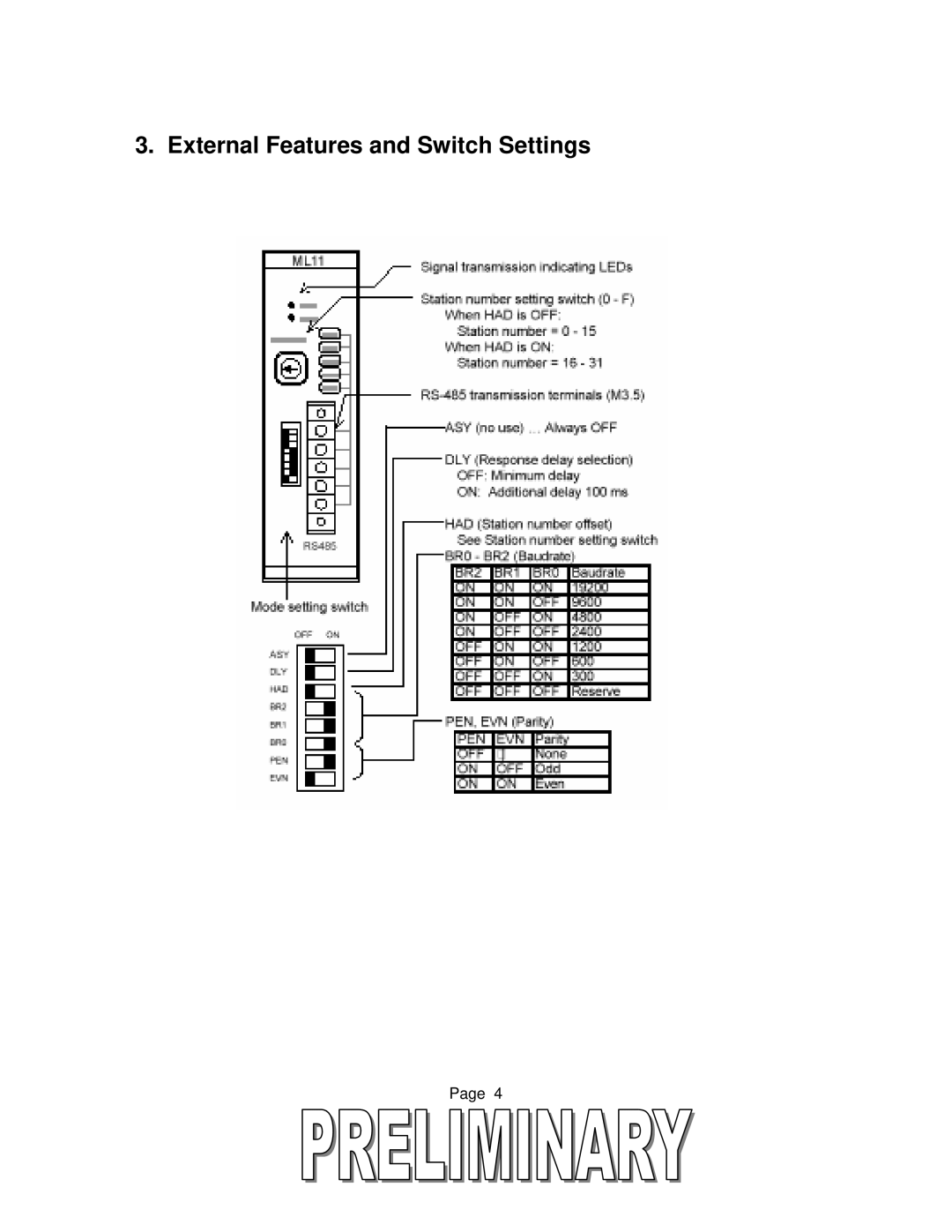
3. External Features and Switch Settings
Page 4
Page 9
Page 11
Page 10
Image 10
Page 9
Page 11
Contents
Prosec T2-Series
Important Information
Safety Precautions
Hazard Classifications
About This Guide
Contents
Page
Overview
To 1 Configuration
System Configuration
Modbus Module
To N Configuration
External Features and Switch Settings
Specifications
Modbus Module Operation Modbus Commands
Modbus Function Code T2 Command
Data Type Attribute Modbus No Offset
Modbus Data Types and T2 Register Mapping
Reg/Device Address T2
Restricted Registers
Modbus T2 Address mapping Example
Modbus Module DIP Switch Settings
Modbus Module Setup
Station Number
BR2 BR1 BR0
Reserved
Parity
ASY and DLY switches
Parity Check
PEN EVN
Example Configuration Settings
ASY DLY Had BR2 BR1 BR0 PEN EVN
Wiring Connection to the Modbus Module
CPU Setup for the Modbus Module
If the LED indicators are not flashing, check the following
Trouble Shooting
If the LED indicators are on solid
Additional References
Toshiba International Corporation Toshiba Corporation
Toshiba do BRASIL, S.A
Top
Page
Image
Contents