System Configuration
T 2E CPU Unit Configuration
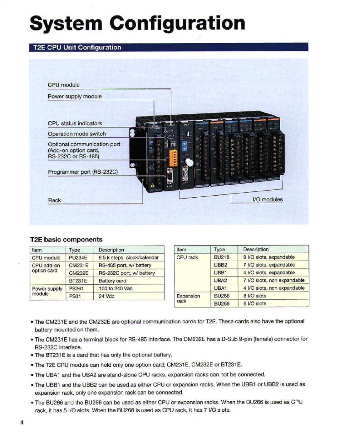
CPU module
Operation mode switch
Optional communication port
Rack
T2F_ basic | components |
| Type | Description | |||
[Iiarn | ; | Type | _ | Description | [t13m | ||
CPU | I | PU234E | 8 .5 k steps, clock/calendar | CPU rack | BU218 | 8 110 sIcIs, expandable | |
CPU |
| M231 C |
| UBB2 | 7 l/O slots, expandable _ | ||
option card | ...CM232E | R9 232C port wl battery |
| UBI31 | 4 110 S1O(Sr Oxparldable | ||
|
| BT231 | E | Battery card |
| _ UBA2 | 7110 slots . non expandable |
Power supply |
| P S261 |
| 100 to 240 Vac |
| UBA1 | 4 110 slots, non expandable |
module |
| 1 |
| 24 Vdc | Expansion | RU26B | 8 I/O slots |
|
|
|
|
| rack | BU266 | 6 I/O slots |
|
|
|
|
|
| ||
•The CM 31E and the CM232E are optional communication cards for T2E. These cards also have the optional battery mounted on them .
*The CM231 E has a terminal block for
*The BT231 E is a card that has only the optional battery_
• | The T2E CPU module can hold only one option card: M 31 E, CM232E or BT231 E . |
• | The UBA1 and the UBA2 are |
•The UB81 and the UBB2 can be used as either CPU or expansion racks . When the UBB1 or UBB Is used as expansion rack. only one expansion reek can be connected .
•The BU266 and the BU268 can be used as either GP U or expansion racks. When the BU266 is used as CPU rack, it has 5 VO slots_ When the BU 66 is used as CPU rack, it has 7 1/0 slots_
4