Gigabit Smart Switch
Cable |
| Pave Way |
|
| Min Parallel |
|
|
| Length (mm1 | ||
|
|
|
|
| |
|
|
|
|
|
|
|
| Parallel cabling | 300 | ||
2~5kVA |
|
|
|
|
|
| One is in the grounded metal raceway or metal pipe | 150 | |||
powerline |
|
|
|
|
|
| The both are in the grounded metal raceway or metal | 80 | |||
|
| ||||
|
| pipe |
|
| |
|
|
|
|
| |
|
|
|
|
|
|
|
| Parallel cabling | 600 | ||
>5kVA |
|
|
|
|
|
| One is in the grounded metal raceway or metal pipe | 300 | |||
powerline |
|
|
|
|
|
| The both are in the grounded metal raceway or metal | 150 | |||
|
| ||||
|
| pipe |
|
| |
|
|
|
|
| |
|
|
|
|
|
|
|
|
|
|
| |
Device |
| Min Distance (m1 |
|
| |
|
|
|
|
| |
Switch case |
| 1.00 |
|
| |
|
|
|
| ||
Transformer room | 2.00 |
|
| ||
|
|
|
| ||
Elevator tower | 2.00 |
|
| ||
|
|
|
| ||
2.00 |
|
| |||
|
|
|
|
|
|
3333 Connect to Ground
Connecting the device to ground is to quickly release the lightning
In different environments, the device may be grounded differently. The following will instruct you to connect the device to the ground in two ways, connecting to the grounding bar or connecting to the ground via the power cord. Please connect the device to ground in the optimum way according to your specific operation environment.
■■ Connecting to the Grounding Bar
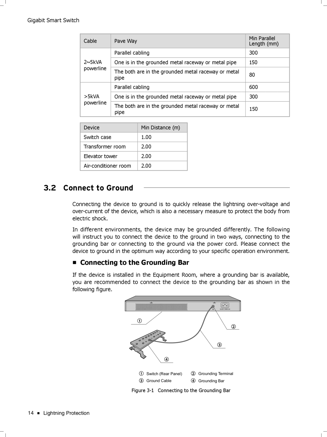
If the device is installed in the Equipment Room, where a grounding bar is available, you are recommended to connect the device to the grounding bar as shown in the following figure.
Switch (Rear Panel) | Grounding Terminal |
Ground Cable | Grounding Bar |
FFFFFFFFFFF Connecting to the Grounding Bar
14 ![]() Lightning Protection
Lightning Protection