1.3Conventions
The AP or
Parameters provided in the pictures are just references for setting up the product, which may differ from the actual situation.
You can set the parameters according to your demand.
Chapter 2 Hardware Installation
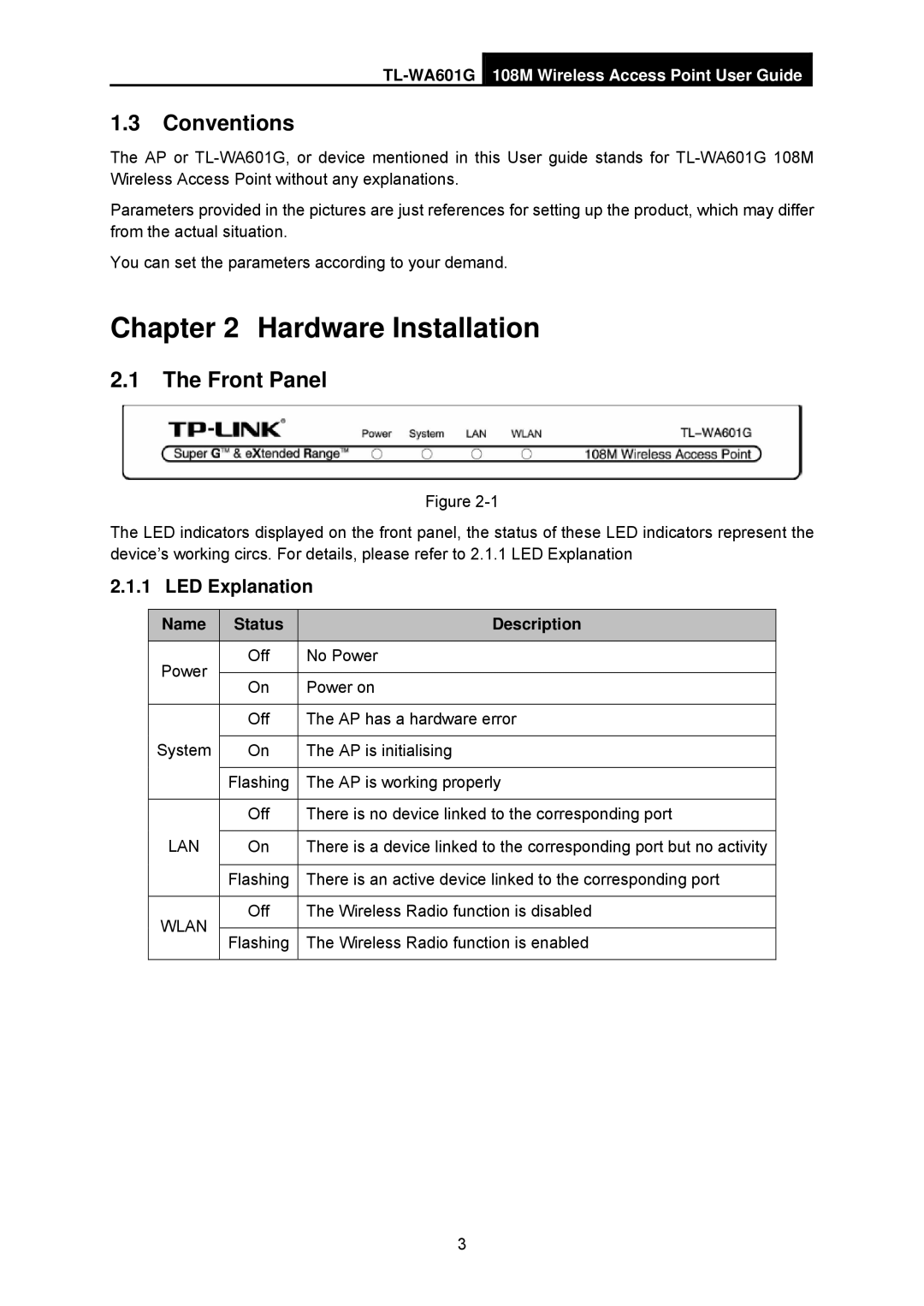
2.1The Front Panel
Figure
The LED indicators displayed on the front panel, the status of these LED indicators represent the device’s working circs. For details, please refer to 2.1.1 LED Explanation
2.1.1 LED Explanation
| Name |
| Status |
| Description |
|
|
|
|
|
|
| Power |
| Off | No Power | |
|
|
|
|
| |
|
| On |
| Power on | |
|
|
|
| ||
|
|
|
|
| |
|
|
| Off | The AP has a hardware error | |
| System |
|
|
|
|
|
| On |
| The AP is initialising | |
|
|
|
|
| |
|
|
| Flashing | The AP is working properly | |
|
|
|
|
| |
|
|
| Off | There is no device linked to the corresponding port | |
| LAN |
|
|
|
|
|
| On |
| There is a device linked to the corresponding port but no activity | |
|
|
|
|
| |
|
|
| Flashing | There is an active device linked to the corresponding port | |
|
|
|
|
| |
| WLAN |
| Off | The Wireless Radio function is disabled | |
|
|
|
|
| |
|
| Flashing | The Wireless Radio function is enabled | ||
|
|
| |||
|
|
|
|
|
|
3
