CA8900
|
| WIRES: |
|
|
|
| C W RH G | ||
3 Wire |
| |||
Heat |
| From | 3 Wire | |
| Furnace | |||
+C |
|
|
| Heat +C |
|
| |||
C | W | RH | G |
|
7
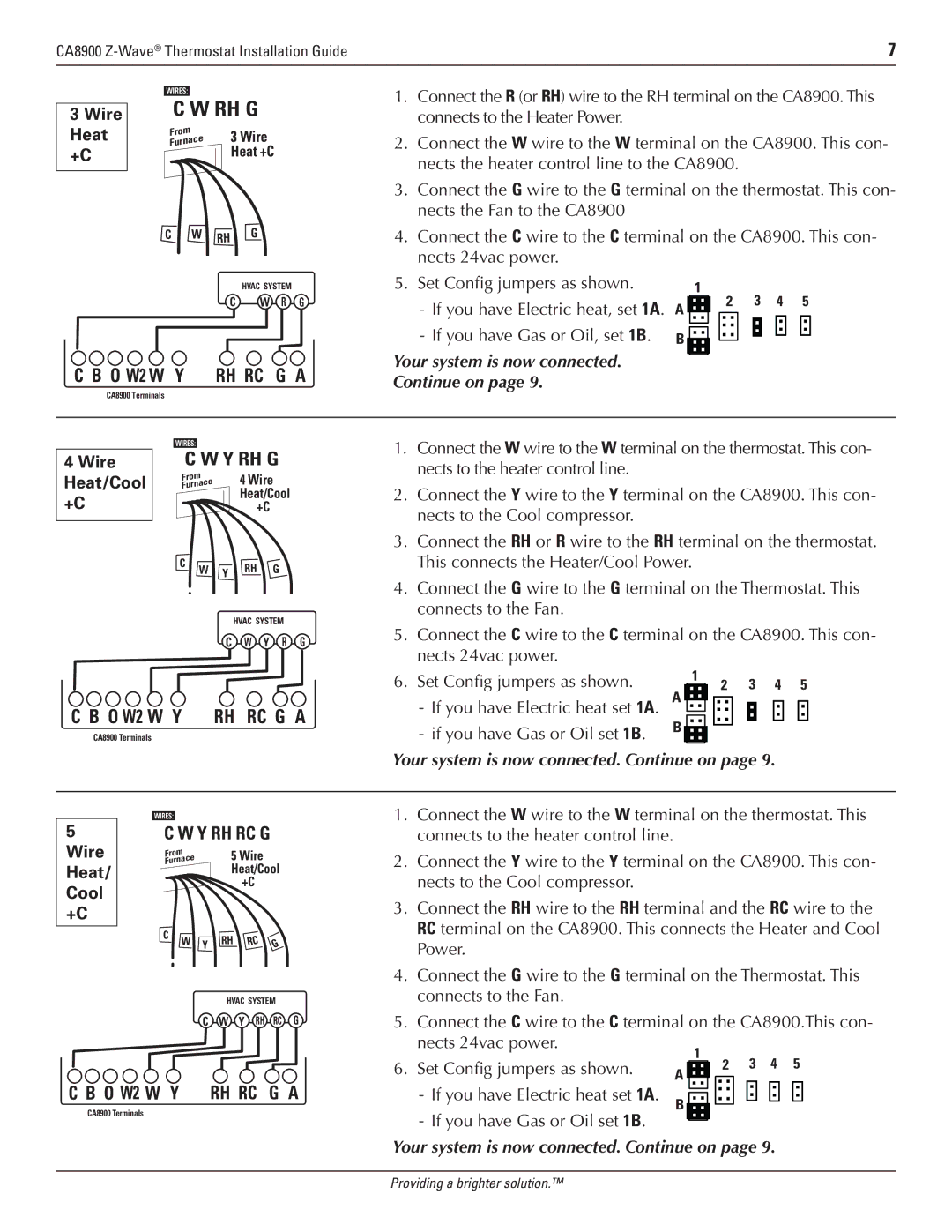
1.Connect the R (or RH) wire to the RH terminal on the CA8900. This connects to the Heater Power.
2.Connect the W wire to the W terminal on the CA8900. This con- nects the heater control line to the CA8900.
3.Connect the G wire to the G terminal on the thermostat. This con- nects the Fan to the CA8900
4.Connect the C wire to the C terminal on the CA8900. This con- nects 24vac power.
OPTIONAL POWER
HVAC SYSTEM
C W R G
5. Set Config jumpers as shown. |
| 1 | 2 |
| 3 | 4 | 5 | |
A |
|
| ||||||
|
|
|
|
|
|
| ||
| B |
|
|
|
|
|
|
|
|
|
|
|
|
|
| ||
|
|
|
|
|
|
| ||
|
|
|
|
|
|
| ||
|
|
|
|
|
|
| ||
C B O W2 W Y RH RC G A
CA8900 Terminals
|
| WIRES: | W Y RH G | ||
| C | ||||
4 Wire |
| ||||
Heat/Cool |
| Furnace |
| 4 Wire | |
|
| From |
|
| |
+C |
|
|
|
| Heat/Cool |
|
|
|
| ||
| C |
|
| +C | |
|
| ||||
|
| W | Y | RH G | |
|
| ||||
|
|
| |||
|
|
|
| ||
HVAC SYSTEM
C W Y R G
C B O W2 W Y RH RC G A
CA8900 Terminals
WIRES:
5C W Y RH RC G
Wire | Furnace |
| 5 Wire |
| ||
| From |
|
|
|
| |
Heat/ |
|
|
| Heat/Cool | ||
Cool |
|
|
|
| +C |
|
|
|
|
|
|
| |
+C |
|
|
|
|
|
|
| C | W | Y | RH | RC | G |
|
| |||||
|
|
| ||||
|
|
|
| HVAC SYSTEM | ||
|
|
| C | W Y RH | RC G | |
C B O W2 W Y RH RC G A
CA8900 Terminals
Your system is now connected.
Continue on page 9.
1.Connect the W wire to the W terminal on the thermostat. This con- nects to the heater control line.
2.Connect the Y wire to the Y terminal on the CA8900. This con- nects to the Cool compressor.
3.Connect the RH or R wire to the RH terminal on the thermostat. This connects the Heater/Cool Power.
4.Connect the G wire to the G terminal on the Thermostat. This connects to the Fan.
5.Connect the C wire to the C terminal on the CA8900. This con- nects 24vac power.
6. Set Config jumpers as shown. |
|
| 1 |
| 2 |
| 3 4 5 | |
|
|
|
|
|
| |||
|
|
|
|
|
| |||
|
|
|
|
|
| |||
B |
|
|
|
|
|
|
| |
|
|
|
|
|
| |||
|
|
|
|
|
|
| ||
|
|
|
|
|
|
|
| |
Your system is now connected. Continue on page 9. | ||||||||
1.Connect the W wire to the W terminal on the thermostat. This connects to the heater control line.
2.Connect the Y wire to the Y terminal on the CA8900. This con- nects to the Cool compressor.
3.Connect the RH wire to the RH terminal and the RC wire to the RC terminal on the CA8900. This connects the Heater and Cool Power.
4.Connect the G wire to the G terminal on the Thermostat. This connects to the Fan.
5.Connect the C wire to the C terminal on the CA8900.This con-
nects 24vac power. |
|
|
| 1 |
|
|
|
|
|
6. Set Config jumpers as shown. |
|
|
|
| 2 | 3 | 4 | 5 | |
A |
|
|
| ||||||
|
|
|
|
|
|
| |||
|
|
|
|
|
|
| |||
|
|
|
|
|
|
|
| ||
|
|
|
|
|
|
|
| ||
|
|
|
|
|
| ||||
|
|
|
|
|
|
|
| ||
|
|
|
|
|
|
|
|
| |
|
|
|
|
|
|
|
|
| |
Your system is now connected. Continue on page 9.
Providing a brighter solution.™