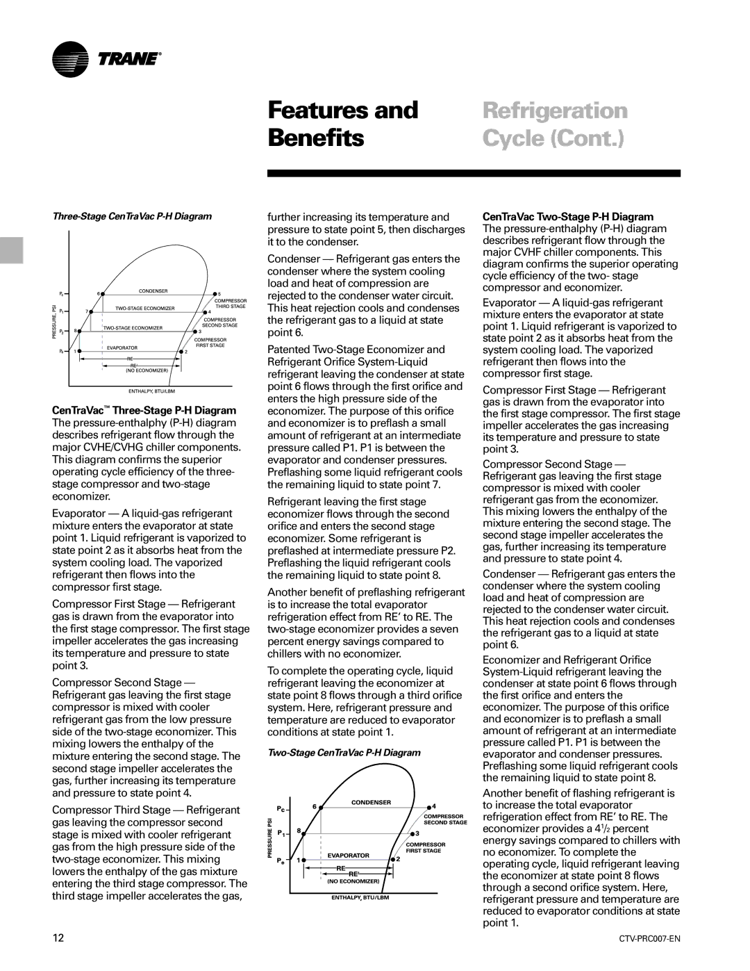
Three-Stage CenTraVac P-H Diagram
CenTraVac™ Three-Stage P-H Diagram The pressure-enthalphy(P-H) diagram describes refrigerant flow through the major CVHE/CVHG chiller components. This diagram confirms the superior operating cycle efficiency of the three- stage compressor and two-stage economizer.
Evaporator — A liquid-gas refrigerant mixture enters the evaporator at state point 1. Liquid refrigerant is vaporized to state point 2 as it absorbs heat from the system cooling load. The vaporized refrigerant then flows into the compressor first stage.
Compressor First Stage — Refrigerant gas is drawn from the evaporator into the first stage compressor. The first stage impeller accelerates the gas increasing its temperature and pressure to state point 3.
Compressor Second Stage — Refrigerant gas leaving the first stage compressor is mixed with cooler refrigerant gas from the low pressure side of the two-stage economizer. This mixing lowers the enthalpy of the mixture entering the second stage. The second stage impeller accelerates the gas, further increasing its temperature and pressure to state point 4.
Compressor Third Stage — Refrigerant gas leaving the compressor second stage is mixed with cooler refrigerant gas from the high pressure side of the two-stage economizer. This mixing lowers the enthalpy of the gas mixture entering the third stage compressor. The third stage impeller accelerates the gas,
further increasing its temperature and pressure to state point 5, then discharges it to the condenser.
Condenser — Refrigerant gas enters the condenser where the system cooling load and heat of compression are rejected to the condenser water circuit. This heat rejection cools and condenses the refrigerant gas to a liquid at state point 6.
Patented Two-Stage Economizer and Refrigerant Orifice System-Liquid refrigerant leaving the condenser at state point 6 flows through the first orifice and enters the high pressure side of the economizer. The purpose of this orifice and economizer is to preflash a small amount of refrigerant at an intermediate pressure called P1. P1 is between the evaporator and condenser pressures. Preflashing some liquid refrigerant cools the remaining liquid to state point 7.
Refrigerant leaving the first stage economizer flows through the second orifice and enters the second stage economizer. Some refrigerant is preflashed at intermediate pressure P2. Preflashing the liquid refrigerant cools the remaining liquid to state point 8.
Another benefit of preflashing refrigerant is to increase the total evaporator refrigeration effect from RE’ to RE. The two-stage economizer provides a seven percent energy savings compared to chillers with no economizer.
To complete the operating cycle, liquid refrigerant leaving the economizer at state point 8 flows through a third orifice system. Here, refrigerant pressure and temperature are reduced to evaporator conditions at state point 1.
Two-Stage CenTraVac P-H Diagram
CenTraVac Two-Stage P-H Diagram The pressure-enthalphy(P-H) diagram describes refrigerant flow through the major CVHF chiller components. This diagram confirms the superior operating cycle efficiency of the two- stage compressor and economizer.
Evaporator — A liquid-gas refrigerant mixture enters the evaporator at state point 1. Liquid refrigerant is vaporized to state point 2 as it absorbs heat from the system cooling load. The vaporized refrigerant then flows into the compressor first stage.
Compressor First Stage — Refrigerant gas is drawn from the evaporator into the first stage compressor. The first stage impeller accelerates the gas increasing its temperature and pressure to state point 3.
Compressor Second Stage — Refrigerant gas leaving the first stage compressor is mixed with cooler refrigerant gas from the economizer. This mixing lowers the enthalpy of the mixture entering the second stage. The second stage impeller accelerates the gas, further increasing its temperature and pressure to state point 4.
Condenser — Refrigerant gas enters the condenser where the system cooling load and heat of compression are rejected to the condenser water circuit. This heat rejection cools and condenses the refrigerant gas to a liquid at state point 6.
Economizer and Refrigerant Orifice System-Liquid refrigerant leaving the condenser at state point 6 flows through the first orifice and enters the economizer. The purpose of this orifice and economizer is to preflash a small amount of refrigerant at an intermediate pressure called P1. P1 is between the evaporator and condenser pressures. Preflashing some liquid refrigerant cools the remaining liquid to state point 8.
Another benefit of flashing refrigerant is to increase the total evaporator refrigeration effect from RE’ to RE. The economizer provides a 41/2 percent energy savings compared to chillers with no economizer. To complete the operating cycle, liquid refrigerant leaving the economizer at state point 8 flows through a second orifice system. Here, refrigerant pressure and temperature are reduced to evaporator conditions at state point 1.