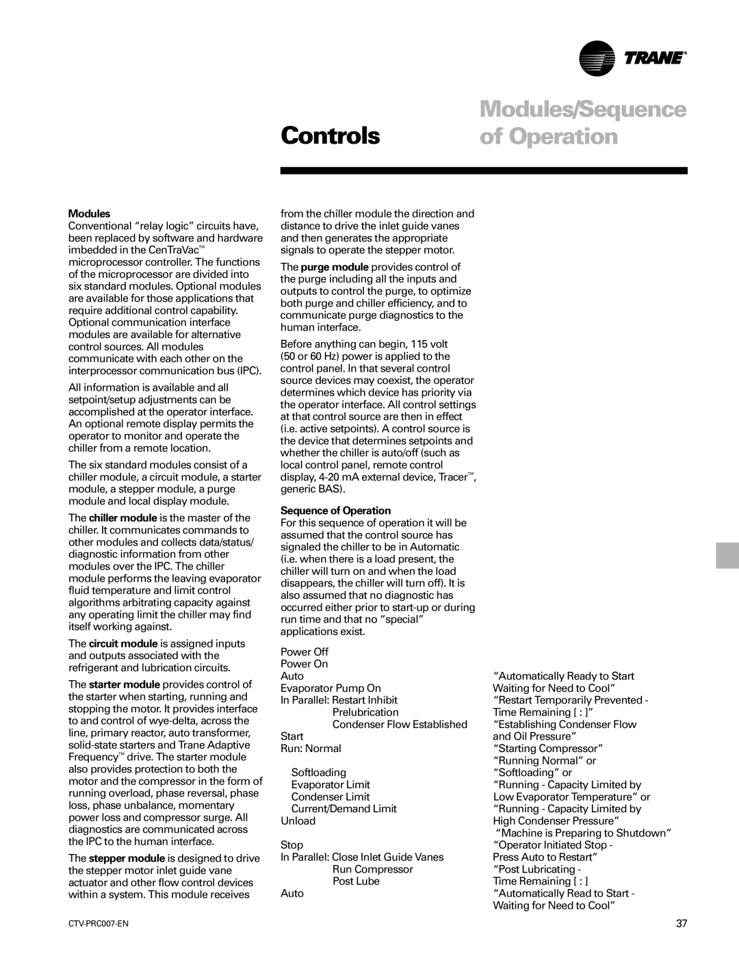
ctv-prc007-en specifications
The Trane CTV-PRC007-EN is an advanced air conditioning unit that epitomizes efficiency and reliability in temperature control. Designed for commercial and industrial applications, this unit stands out with a multitude of features aimed at enhancing performance, energy savings, and sustainability.One of the key characteristics of the CTV-PRC007-EN is its high cooling and heating capacities, allowing it to cater to a variety of environments. The unit utilizes a scroll compressor, known for its energy efficiency and durable design, which contributes to substantial energy savings over time. The inclusion of variable speed technology further optimizes energy use by adjusting to the specific cooling or heating demands of the space.
Equipped with Trane’s proprietary Sintesis technology, the CTV-PRC007-EN offers superior temperature control while minimizing noise levels. This feature makes it ideal for settings where quiet operation is essential, such as offices, hotels, and conference rooms. The unit’s sound-dampening design reduces operational noise, ensuring a comfortable environment for occupants.
Another significant advantage of the CTV-PRC007-EN is its advanced control system. The integration of Smart Temperature Management allows for precise monitoring and adjustment, enhancing the overall user experience. Additionally, the system is compatible with various building management systems, enabling remote monitoring and control, which can significantly reduce operational costs and improve efficiency.
The CTV-PRC007-EN also embraces eco-friendly refrigerants, aligning with global sustainability goals. By using refrigerants with low global warming potential, Trane demonstrates its commitment to reducing environmental impact while maintaining high performance.
Maintenance is straightforward with the CTV-PRC007-EN. The unit's robust design includes accessible components that simplify servicing, helping to minimize downtime and operational costs. It comes with a comprehensive warranty, underscoring Trane’s confidence in the durability and reliability of its products.
In conclusion, the Trane CTV-PRC007-EN stands as a testament to cutting-edge technology in HVAC solutions. With its energy efficiency, advanced control systems, quiet operation, and eco-friendly features, it is an ideal choice for businesses seeking effective climate control solutions that do not compromise on sustainability or performance.

