Manuals
/
Trane
/
Household Appliance
/
Air Conditioner
Trane
RTAC 140-400 ton units (50 HZ), Series R Air-Cooled Helical Rotary Liquid Chillers manual 206
Models:
RTAC 140-400 ton units (50 HZ)
RTAC 140-500 ton units (60 Hz)
Series R Air-Cooled Helical Rotary Liquid Chillers
1
206
252
252
Download
252 pages
38.49 Kb
203
204
205
206
207
208
209
210
<
>
Install
System Schematic
Evaporator tube replacement
Maintenance
Configuration View
Power Supply Wiring
Chilled Water Reset CWR
Diagnostic Screen
Procedure
Default Assignments Relay
Page 206
Image 206
206
RTAC-SVX01F-EN
Page 205
Page 207
Page 206
Image 206
Page 205
Page 207
Contents
Models
Series R Air-Cooled Helical Rotary Liquid Chillers
January
Rtac 140-500 ton units 60 Hz Rtac 140-400 ton units 50 Hz
Contains Refrigerant
Environmental Concerns
Responsible Refrigerant Practices
Table of Contents
Controls Interface
Installation Electrical
Operating Principles
137
106
126
144
165
149
155
Unit Identification Nameplates
General Information
Literature History
Loose Parts Inventory
Inspection Checklist
Unit Inspection
Unit Description
Typical Rtac Unit
General Data 140-250 Ton 60 Hz Units Standard Efficiency
STD
General Data 275- 500 Ton 60 Hz Units Standard Efficiency
General Data 140-400 Ton 60 Hz Units High Efficiency
High
General Data 120-400 Ton 50 Hz Units-Standard Efficiency
General Data 120-400 Ton 50 Hz Units-High Efficiency
General Information
RTAC-SVX01F-EN
Unit Dimensions 225-250 Ton High Efficiency, 60 Hz
RTAC-SVX01F-EN
RTAC-SVX01F-EN
Unit Dimensions 300 Ton High Efficiency, 50 and 60 Hz
RTAC-SVX01F-EN
RTAC-SVX01F-EN
RTAC-SVX01F-EN
RTAC-SVX01F-EN
RTAC-SVX01F-EN
Model Number Coding System
Unit Model Number
Coop
Nameplates
Installation Mechanical
Installation Responsibilities
Outdoor Unit Nameplate
General
Setting the Unit
Storage
Location Requirements
Lifting the Unit Package and Remote 30-36-foot Base
Aluminum Fins
Copper Fins
Installation Mechanical
Remote Evaporator Aluminum Fins
Remote Evaporator Copper Fins
Isolation and Sound Emission
Unit Isolator Locations
Noise Considerations
Foundation
Clearances
Recommended Unit Clearances 18-21 foot bases
Recommended Evaporator Clearance
Drainage
Evaporator Damage
Unit Isolation and Leveling
Evaporator Water Piping
Entering Chilled Water Piping
Evaporator Flow Switch
Use Piping Strainers
Leaving Chilled Water Piping
Evaporator Water Pressure Drop Rtac 140 250 Ton
Evaporator Water Pressure Drop
Water-Side Pressure Drop vs Flow Rate
Proper Water Treatment
Evaporator Water Pressure Drop Rtac 250 500 Ton
Water Pressure Gauges
Suggested Piping for Typical Rtac Evaporator
Water Pressure Relief Valves
Procedure
Shell Damage
Freeze Protection
Specials
Glycol Recommendations
Recommended Low Evaporator Refrigerant Cutout and % Glycol
Equipment Damage
Installation Mechanical Remote Evaporator Option
System Configuration and Interconnecting Refrigerant Piping
Installation Mechanical Remote Evaporator Option
Remote Evaporator Installations
Circuit Identification
Line Sizing
Rtac 140-250 Ton Rem ote Evaporator Liquid Line Sizes
Liquid Line Sizing Steps
Required Length of Field Installed Suction Accumulator
Example Liquid Line Sizing
Ton circuit 85ton circuit
Suction Line Sizing Steps
Example Suction Line Sizing
Suction Accumulator Sizing
Piping Installation Procedures
Hazardous Gas
Example of Suction Accumulator Line Sizing
Refrigerant Pressure Relief Valve Venting
Hazardous Gases
Refrigerant Sensors
Leak Test and Evacuation
Hazard of Explosion
Remote Evaporator
Refrigerant and Additional Oil Charge
Refrigerant Charge Determination
Oil Charge Determination
Use Copper Conductors Only
Installation Electrical
Hazardous Voltage w/Capacitors
General Recommendations
Hacr
Unit Wiring Motor Data Max. Fuse
300
450
FLA Rtac
Unit Wiring Motor Data Max. Fuse Compressor Each
575/60/3
200/60/3
Rec. Time Power Breaker or
200/60/3 960 1200 386-386 2156-2156 701-701
200/60/3 960522 1200/800 1200/700
200/60/3 960/960 1200/1200 12001200
Installer-Supplied Components
Power Supply Wiring
Control Power Supply
Starter Panel
Chilled Water Flow Pump Interlock
Interconnecting Wiring
Heat Tape
Chilled Water Pump Control
Alarm and Status Relay Outputs Programmable Relays
Default Assignments Relay
Low Voltage Wiring
Relay Assignments Using TechView
Ice Building Option
External Auto/Stop
External Circuit Lockout Circuit #1 and Circuit #2
External Chilled Water Setpoint Ecws Option
External Current Limit Setpoint Ecls Option
Chilled Water Reset CWR
Wiring Examples for Ecls and Ecws
Where
Return
Outdoor
Communications Interface options
Installation Recommendations
Wire Size Maximum Length of Communication Wire
Optional Tracer Communications Interface
Outputs Variable type SNVTType
R134a
Operating Principles
Refrigeration Cycle
System Schematic
Condenser and Subcooler
Refrigerant R134a
Compressor
Oil System
Expansion Valve
Evaporator
KEY
Controls Interface
Controls Interface
CH530 Communications Overview
DynaView Interface
Radio Buttons
Cancel Hot Links
Key Functions
Spin Value Buttons
Display Screens
Basic Screen Format
Front Panel Lockout Feature
Front Panel Display During Cold Ambients
Modes Screen
Modes Chiller
Chiller Modes Description Top Level Mode Sub-modes
Controls Interface
Circuit Modes Description Top Level Mode Sub-modes
Controls Interface
Compressor Modes Description Top Level Mode Sub-modes
Compressor Screen
Chiller Screen Description Resolution Units
Chiller Screen
Compressor Screen Description Resolution Units
Refrigerant Screen
Setpoint Screen
Refrigerant Screen Description Resolution Units
Setpoint Screen Description Resolution or Text Units
Option Conditions Explanation
Diagnostic Screen
Setpoint Options/Conditions Displayed
Units
Power-Up
Display Formats
Languages
TechView
Minimum PC requirements to install and operate TechView
Unit View
108
Compressor Service View
Status View
Status View
Status View Items Tab Text Units
RLA
112
Setpoint View
Setpoint View
Setpoint Numeric Panel
115
116
Diagnostics View
Diagnostic View
Configuration View
Configuration View
Configuration View Items Tab Default Description
120
121
Software View
Software View
Binding View
Binding View
Instructions for First Time TechView Users
Software Download
Replacing or Adding Devices
125
Diagnostics
5EF
127
128
129
130
131
132
133
134
135
136
Receiving
Installation Checklist
Pre-Start Checkout
Unit Location and Mounting
Live Electrical Components
Information in Interconnecting Wiring
Electrical Wiring
Connections
Compressor Damage
Unit Voltage Power Supply
Unit Voltage Imbalance
Unit Voltage Phasing
Water System Pressure Drop
Phase Seq. Lead Terminal
Water System Flow Rates
CH530 Set-Up
Unit Start-Up Procedures
Daily Unit Start-Up
Seasonal Unit Start-Up Procedure
Refrigerant
System Restart After Extended Shutdown
Chilled Water Pump
Unit Shutdown Procedures
Extended Shutdown Procedure
Temporary Shutdown And Restart
Unit Shutdown Procedure
Disconnect Power
Monthly Maintenance
Periodic Maintenance
Weekly Maintenance
Annual Maintenance
Hazardous Voltage w/Capacitors
Rtac Start-up Test Log
Circuit 1 Control
Circuit Control
Compressor 1A Tab Compressor 1B Tab
Chiller Tab
Circuit 1 Tab Circuit 2 Tab
Comments
Compressor 2A Tab Compressor 2B Tab
Maintenance Procedures
Refrigerant and Oil Charge Management
R134a Field Charging Procedure
Field Refrigerant Charging Procedure
Adding charge
High side charge isolation procedure
Charge Isolation in the high or low side of system
Low side charge isolation procedure
Returning unit to running condition
Lubrication System
Refrigerant Filter Replacement Procedure
Oil Charging Procedure
Oil System Schematic
Factory initial Oil Charging Procedure
Field Oil Charging Procedure
Evaporator tube replacement
Compressor Replacement
Hazardous Voltage
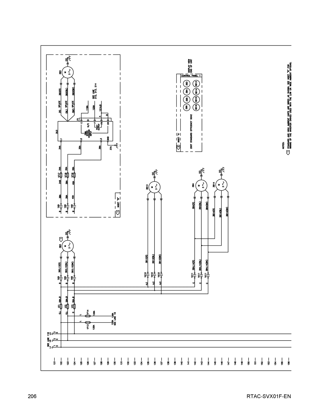
Unit Wiring
Drawing Number Description
166
167
168
169
170
171
172
173
174
175
176
177
178
179
180
181
182
183
184
185
186
187
188
189
190
191
192
193
194
195
196
197
198
199
200
201
202
203
204
205
206
207
208
209
210
211
212
213
214
215
216
217
218
219
220
221
222
223
224
225
226
227
228
229
230
231
232
233
234
235
236
237
238
239
240
241
242
243
244
245
246
247
248
249
250
Page
RTAC-SVX01F-EN