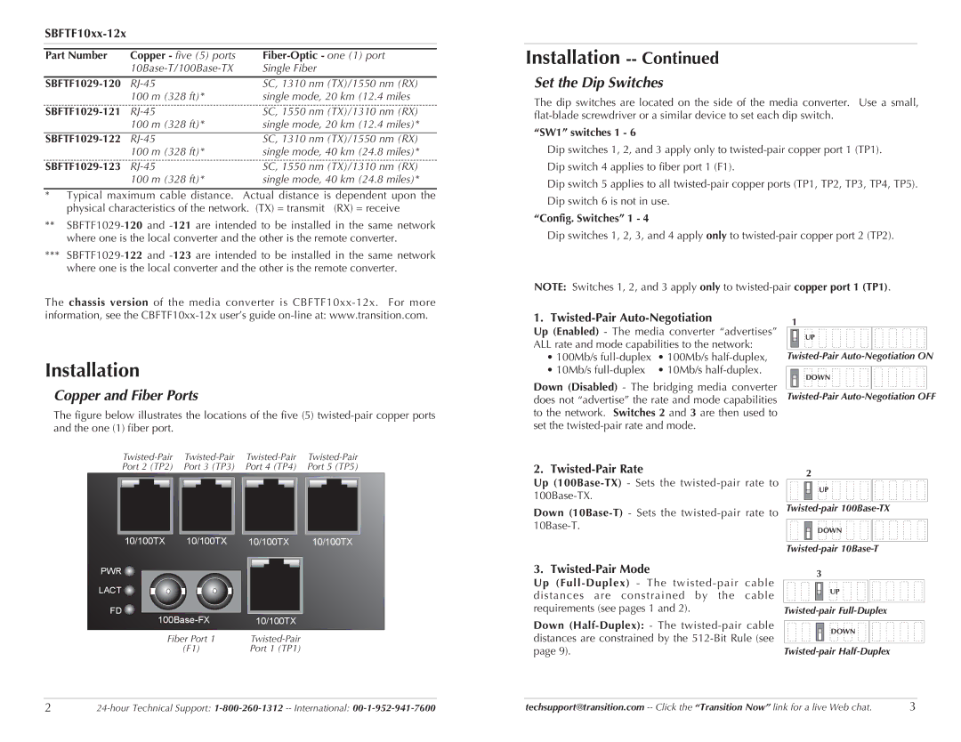
SBFTF1014-120, SBFTF1011-120, SBFTF1025-120, SBFTF1018-120, SBFTF1015-120 specifications
Transition Networks is a leading provider of network connectivity solutions, and their SBFTF series switches exemplify the company’s commitment to high performance and reliability. The SBFTF1016-120, SBFTF1025-120, SBFTF1013-120, SBFTF1015-120, and SBFTF1014-120 are part of this series, designed for a variety of applications in industrial environments.These switches are equipped with advanced features that cater to the demanding requirements of modern communication networks. One of the key characteristics of the SBFTF series is their versatility in supporting both copper and fiber connections. This flexibility ensures smooth integration into existing infrastructures while enabling expanded networking capabilities.
The SBFTF1016-120 model stands out with its 16-port configuration, allowing for substantial connectivity options. It supports both Fast Ethernet and Gigabit Ethernet, making it suitable for various data transfer needs. The inclusion of PoE (Power over Ethernet) capabilities facilitates efficient power management, especially for devices like IP cameras and wireless access points.
In contrast, the SBFTF1025-120 model features a 25-port layout, perfect for environments requiring numerous connections. Its robust design ensures reliability in harsh conditions, making it ideal for industrial settings. Like the other models, it supports multiple media types, enhancing its versatility.
The SBFTF1013-120, SBFTF1015-120, and SBFTF1014-120 models are designed with specific user needs in mind. The SBFTF1013-120 offers 13 ports, focusing heavily on redundancy, which is critical in mission-critical applications. The SBFTF1015-120 features a balance between port density and performance, while the SBFTF1014-120 caters to businesses needing a slightly reduced port count without sacrificing functionality.
All SBFTF series switches are known for their rugged construction, making them suitable for deployment in environments with demanding conditions such as extreme temperatures and vibrations. Alongside their durability, these switches provide high-speed data transmission, low latency, and advanced network management capabilities.
Additionally, management features such as VLAN support, link aggregation, and advanced monitoring tools enhance network efficiency and performance. This makes them not only a reliable choice but also a flexible solution for growing networks in various sectors, including manufacturing, transportation, and smart city applications.
In summary, Transition Networks SBFTF series switches, including the SBFTF1016-120, SBFTF1025-120, SBFTF1013-120, SBFTF1015-120, and SBFTF1014-120, embody innovation, reliability, and functionality in network connectivity. Whether for robust industrial applications or integration into complex network environments, these switches provide an excellent balance of features that cater to diverse requirements.

