SISTF10xx-140-LR(T) / -160-LR(T) / -170-LR(T)
Installation -- Continued
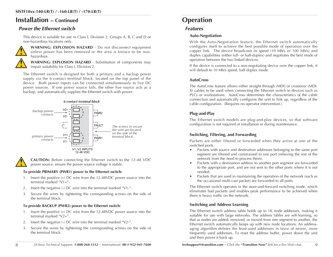
Power the Ethernet switch
This device is suitable for use in Class I, Division 2, Groups A, B, C and D or
WARNING: EXPLOSION HAZARD - Do not disconnect equipment unless power has been removed or the area is known to be non- hazardous.
WARNING: EXPLOSION HAZARD - Substitution of components may impair suitability for Class I, Division 2.
The Ethernet switch is designed for both a primary and a backup power supply via the
Operation
Features
Auto-Negotiation
With the
If the device is connected to a
AutoCross
The AutoCross feature allows either
X)cables to be used when connecting the Ethernet switch to devices such as PLCs or workstations. AutoCross determines the characteristics of the cable connection and automatically configures the unit to link up, regardless of the cable configuration. (Requires no operator intervention.)
backup power |
| V2+ | |
|
| ||
contacts |
| V2- | |
|
| ||
|
|
|
|
primary power |
| V1+ | |
contacts |
|
|
|
| V1- | ||
|
| ||
PWR2
FAULT
PWR1
V1, V2 INPUTS
The screws to secure the wire are located on the side of the terminal block.
Plug-and-Play
The Ethernet switch models are
Switching, Filtering, and Forwarding
Packets are either filtered or forwarded when they arrive at one of the switched ports.
• Packets with source and destination addresses belonging to the same port |
segment are filtered and constrained to one port (relieving the rest of the |
CAUTION: Before connecting the Ethernet switch to the
To provide PRIMARY (PWR1) power to the Ethernet switch:
1.Insert the positive (+) DC wire from the
2.Insert the negative
3.Secure the wires by tightening the corresponding screws on the side of the terminal block.
To provide BACKUP (PWR2) power to the Ethernet switch:
1.Insert the positive (+) DC wire from the
2.Insert the negative
3.Secure the wires by tightening the corresponding screws on the side of the terminal block.
network from the need to process them). |
• Packets with a destination address to another port segment are forwarded |
to the appropriate port, and are not sent to the other ports where it is not |
needed. |
• Packets that are used in maintaining the operation of the network (such as |
the occasional |
The Ethernet switch operates in the
Switching and Address Learning
The Ethernet switch address table holds up to 1K node addresses, making it suitable for use with large networks. The address tables are
8 | techsupport@transition.com | 9 |