Installation
Power over Ethernet (PoE)
The
There are two modes of transmitting 48VDC PoE as defined in IEEE 802.3af: Mode A uses pins 1&2, 3&6 to transmit data and power; Mode B uses pins 4&5, 7&8 to transmit power. These are the spare pairs in
To set A or B PoE Mode, do the following:
1.Remove the 4 screws and pull the cover off the media converter.
2.Locate the 3 header connects J2, J3, and J4.
2 Set jumpers 2, 3, and 4 to the same side, either (S or U). See diagram below.
Operation
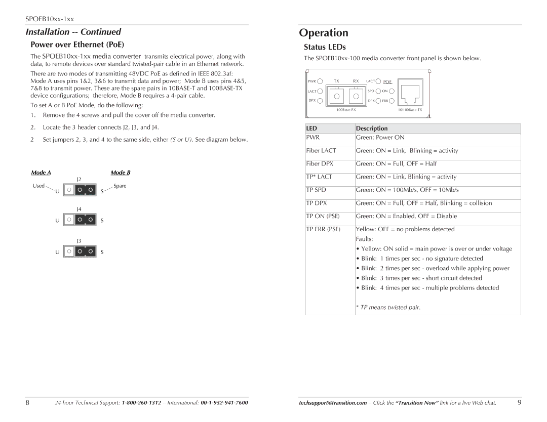
Status LEDs
The
PWR | TX | R X | LACT | POE |
LACT |
|
| SPD | ON |
DPX |
|
| DPX | ERR |
| 100Bas |
| 10/100Bas | |
LED | Description |
PWR | Green: Power ON |
|
|
Fiber LACT | Green: ON = Link, Blinking = activity |
|
|
Fiber DPX | Green: ON = Full, OFF = Half |
Mode A
J2
Used
U
J4
U
J3
U
Mode B
Spare
S
S
S
TP* LACT | Green: ON = Link, Blinking = activity |
|
|
TP SPD | Green: ON = 100Mb/s, OFF = 10Mb/s |
|
|
TP DPX | Green: ON = Full, OFF = Half, Blinking = collision |
|
|
TP ON (PSE) | Green: ON = Enabled, OFF = Disable |
|
|
TP ERR (PSE) | Yellow: OFF = no problems detected |
| Faults: |
| • Yellow: ON solid = main power is over or under voltage |
| • Blink: 1 times per sec - no signature detected |
| • Blink: 2 times per sec - overload while applying power |
| • Blink: 3 times per sec - short circuit detected |
| • Blink: 4 times per sec - multiple problems detected |
| * TP means twisted pair. |
8 | techsupport@transition.com | 9 |