Installation -- continued
Features -- continued
•The
•The
•All SIBTF models include a primary input terminal block (TB) for
•The “MR” models include an auxiliary
See Figure 3.
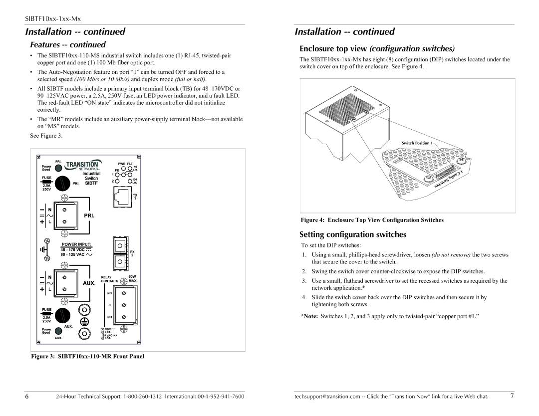
Figure 3: |
Installation -- continued
Enclosure top view (configuration switches)
The
Switch Position 1
Figure 4: Enclosure Top View Configuration Switches
Setting configuration switches
To set the DIP switches:
1.Using a small,
2.Swing the switch cover
3.Use a small, flathead screwdriver to set the recessed switches as required by the network application.*
4.Slide the switch cover back over the DIP switches and then secure it by tightening both screws.
*Note: Switches 1, 2, and 3 apply only to
6 | techsupport@transition.com | 7 |