|
|
|
|
|
|
|
|
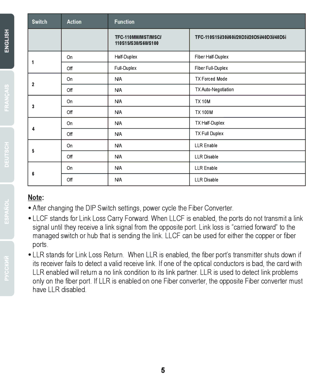
Switch | Action | Function |
|
| |||
|
|
| |||||
|
|
| |||||
|
| 110S15/S30/S60/S100 |
|
| |||
|
|
|
|
|
|
|
|
1 | On |
| Fiber | ||||
|
|
|
|
|
|
| |
Off |
| Fiber | |||||
|
| ||||||
|
|
|
|
|
|
| |
2 | On | N/A |
| TX Forced Mode | |||
|
|
|
|
|
|
| |
Off | N/A |
| TX | ||||
|
| ||||||
|
|
|
|
| |||
3 | On | N/A |
| TX 10M | |||
|
|
|
|
|
|
| |
Off | N/A |
| TX 100M | ||||
|
| ||||||
|
|
|
|
|
| ||
4 | On | N/A |
| TX | |||
|
|
|
|
|
|
| |
Off | N/A |
| TX Full Duplex | ||||
|
| ||||||
|
|
|
|
| |||
5 | On | N/A |
| LLR Enable | |||
|
|
|
|
|
|
| |
Off | N/A |
| LLR Disable | ||||
|
| ||||||
|
|
|
|
| |||
6 | On | N/A |
| LLR Enable | |||
|
|
|
|
|
|
| |
Off | N/A |
| LLR Disable | ||||
|
| ||||||
|
|
|
|
|
|
|
|
|
|
|
|
|
|
|
|
Note:
After changing the DIP Switch settings, power cycle the Fiber Converter.
LLCF stands for Link Loss Carry Forward. When LLCF is enabled, the ports do not transmit a link signal until they receive a link signal from the opposite port. Link loss is “carried forward” to the managed switch or hub that is sending the link. LLCF can be used for either the copper or fiber ports.
LLR stands for Link Loss Return. When LLR is enabled, the fiber port’s transmitter shuts down if its receiver fails to detect a valid receive link. If one of the optical conductors is bad, the card with LLR enabled will return a no link condition to its link partner. LLR is used to detect link problems only on the fiber port. If LLR is enabled on one Fiber converter, the opposite Fiber converter must have LLR disabled.
5