Permanent Connection
In the case of a permanent connection, it is necessary that you install a double pole switch between the hob and the electricity supply (mains), with a minimum gap of 3 mm between the switch contacts and of a type suitable for the required load in compliance with the current electric regulations.
The switch must not break the yellow and green earth cable at any point.
Ensure that the hob supply cord does not come into contact with surfaces with temperatures higher than 50 deg. C.
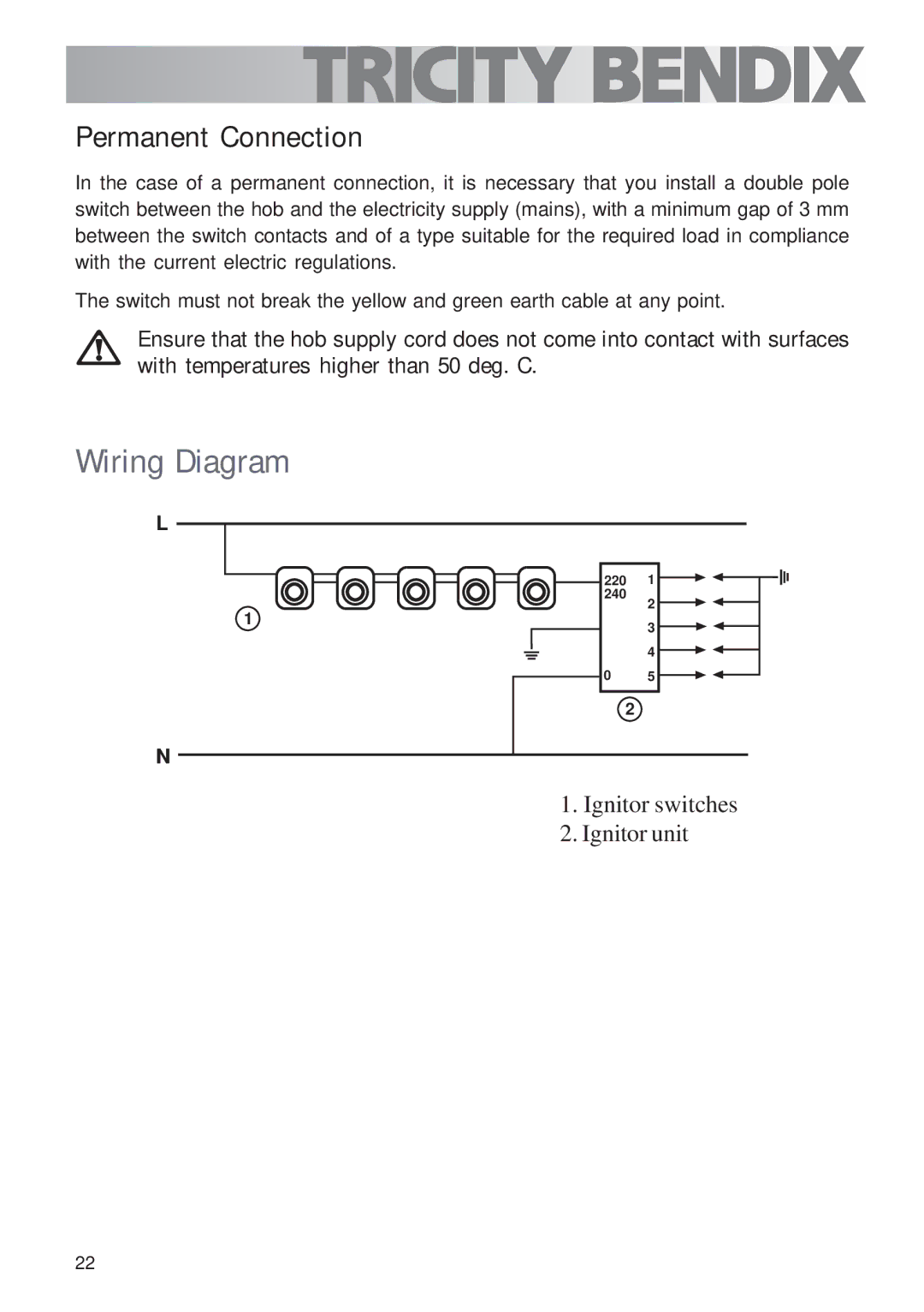
Wiring Diagram
L
1
N
220 1 ![]()
![]()
![]()
![]()
![]()
![]()
240
2
3
4
0 5 ![]()
![]()
2
1.Ignitor switches
2.Ignitor unit
22