Installation
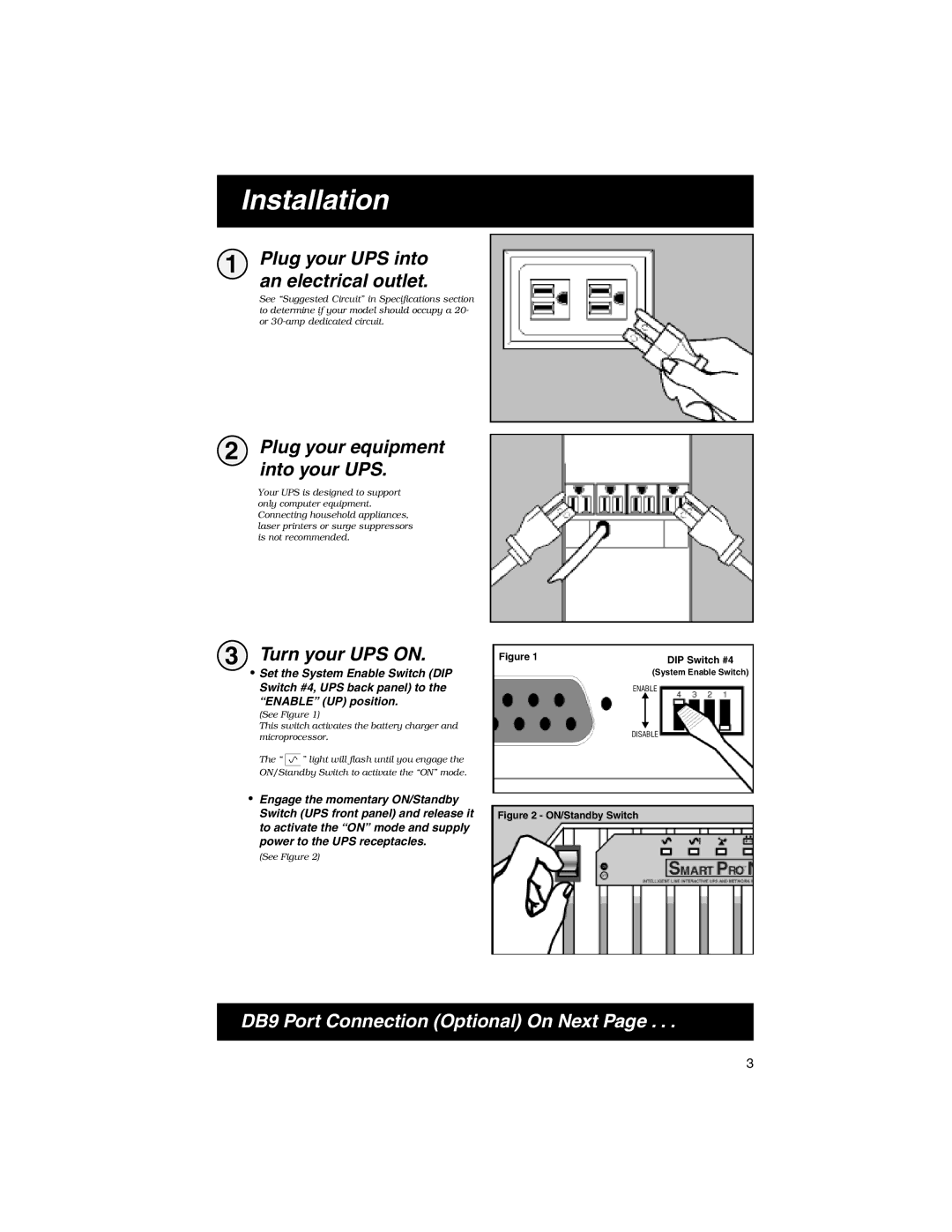
1 Plug your UPS into an electrical outlet.
See “Suggested Circuit” in Specifications section to determine if your model should occupy a 20- or
2 Plug your equipment into your UPS.
Your UPS is designed to support only computer equipment. Connecting household appliances, laser printers or surge suppressors is not recommended.
3 Turn your UPS ON.
· Set the System Enable Switch (DIP Switch #4, UPS back panel) to the
“ENABLE” (UP) position.
(See Figure 1)
This switch activates the battery charger and microprocessor.
The “ ![]() ” light will flash until you engage the ON/Standby Switch to activate the “ON” mode.
” light will flash until you engage the ON/Standby Switch to activate the “ON” mode.
·Engage the momentary ON/Standby Switch (UPS front panel) and release it to activate the “ON” mode and supply power to the UPS receptacles.
(See Figure 2)
Figure 1 |
| DIP Switch #4 |
|
| |
|
| (System Enable Switch) |
| ENABLE | |
|
| |
|
|
|
| DISABLE | |
Figure 2 - ON/Standby Switch
DB9 Port Connection (Optional) On Next Page . . .
3