Manuals
/
Tripp Lite
/
Lawn and Garden
/
Portable Generator
Tripp Lite
200812163
warranty
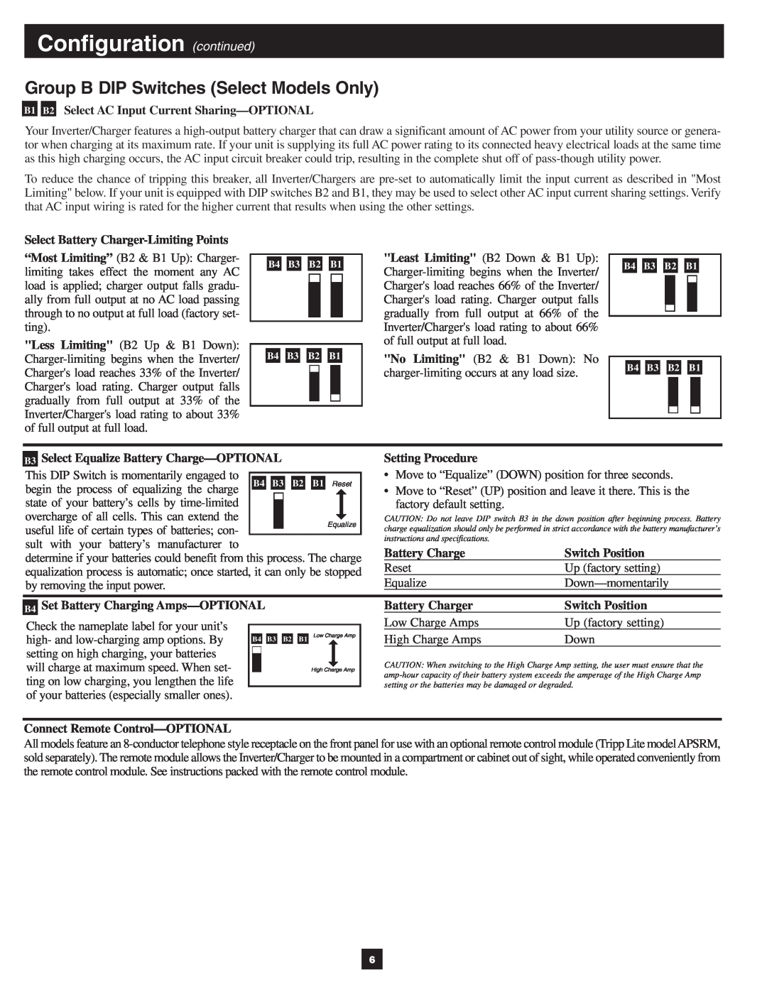
Configuration continued, Group B DIP Switches Select Models Only
Models:
200812163
1
6
12
12
Download
12 pages
33.43 Kb
3
4
5
6
7
8
9
10
Troubleshooting
Indicator Lights Continued
Maintenance
Configuration
Battery Connection Warnings
Feature Identification
Page 6
Image 6
Page 5
Page 7
Page 6
Image 6
Page 5
Page 7
Contents
Better for Your Equipment
Contents
Quiet Mobile Power
Better for Your Batteries
SAVE THESE INSTRUCTIONS
Important Safety Instructions
Battery Connection Warnings
Location Warnings
Feature Identification
Indicator Lights
Switch Modes
Indicator Lights Continued
Operation
Group A DIP Switches All Models
Configuration
Set Configuration DIP Switches
Select Battery Type-REQUIRED
Configuration continued
Group B DIP Switches Select Models Only
Battery Selection
Select Auxiliary Battery Type if any
Example
Mounting
Horizontal Mount
Battery Connection
AC Input/Output Connection
Service
Maintenance
AC Input Connection
WARRANTY REGISTRATION
Troubleshooting
Limited Warranty
SYMPTOM
1111 W. 35th Street, Chicago, IL 60609 USA
773.869.1234 USA 773.869.1212 International
200812163 93-2803_EN
Top
Page
Image
Contents