Battery Connection
Connect your Inverter/Charger to your batteries using the following procedures:
•Connect DC Wiring: Though your Inverter/Charger is a
output capacity is limited by the length and gauge of the cabling running from the battery to the unit. Use the |
|
|
|
| ||||||
shortest length and largest diameter cabling (maximum 2/0 gauge) to fit your Inverter/Charger’s DC Input |
|
|
|
| ||||||
terminals. Shorter and heavier gauge cabling reduces DC voltage drop and allows for maximum transfer of |
|
|
|
| ||||||
current. Your Inverter/Charger is capable of delivering peak wattage at up to 200% of its rated continuous |
|
|
|
|
|
| ||||
|
| DC Connectors |
| |||||||
wattage output for brief periods of time. Heavier gauge cabling should be used when continuously operating |
|
|
| |||||||
|
|
|
|
|
| |||||
heavy draw equipment under these conditions. Tighten your Inverter/ | Recommended Maximum DC Cable Length (ft.) |
| ||||||||
Charger and battery terminals to approximately 3.5 |
|
|
|
|
|
|
|
|
|
|
torque to create an efficient connection and to prevent excessive heating at |
|
|
|
|
|
| AWG/mm |
|
|
|
this connection. Insufficient tightening of the terminals could void your |
|
|
|
|
|
|
|
|
|
|
|
|
|
|
|
|
|
|
|
| |
warranty. |
|
| 6/4.0 |
| 4/5.0 | 2/6.3 | 0/8.3 |
| 00/9.3 | |
• Connect Ground: Using a 8 AWG (3.15 mm) wire or larger directly |
|
|
|
|
|
|
|
|
|
|
Power | 750 | 10 |
| 16 | 26 | 42 |
| 52 | ||
connect the Main Ground Lug to the vehicle’s chassis or earth ground. |
|
| ||||||||
Output |
|
|
|
|
|
|
|
|
| |
See the Feature Identification section to locate the Main Ground Lug on |
|
|
|
|
|
|
|
|
| |
(Watts) | 1250 |
|
|
|
| 16 | 25 |
| 31 | |
your specific Inverter/Charger model. All installations must comply with |
|
|
|
|
| |||||
|
|
|
|
|
|
|
|
|
| |
national and local codes and ordinances. |
|
|
|
|
|
|
|
|
|
|
• Connect Fuse: NEC (National Electrical Code) article 551 requires that you connect your Inverter/Charger’s positive DC Terminal directly to a
WARNING!
•Failure to properly ground your Inverter/Charger to a vehicle’s chassis or earth ground may result in a lethal electrical shock hazard.
•Never attempt to operate your Inverter/Charger by connecting it directly to output from an alternator rather than a battery or battery bank.
•Observe proper polarity with all DC connections.
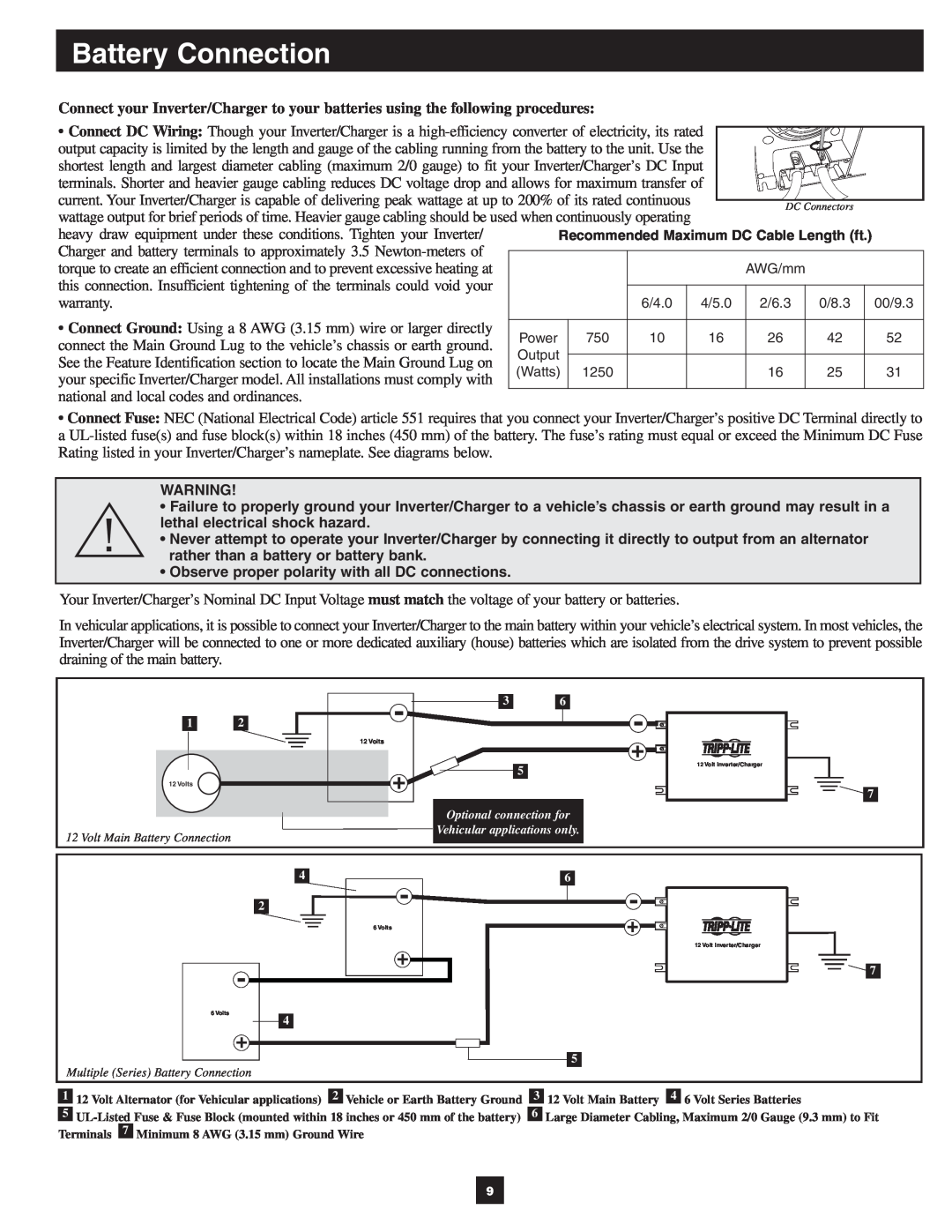
Your Inverter/Charger’s Nominal DC Input Voltage must match the voltage of your battery or batteries.
In vehicular applications, it is possible to connect your Inverter/Charger to the main battery within your vehicle’s electrical system. In most vehicles, the Inverter/Charger will be connected to one or more dedicated auxiliary (house) batteries which are isolated from the drive system to prevent possible draining of the main battery.
1 | 2 |
| 12 Volts |
12 Volts |
|
12 Volt Main Battery Connection
3 6
5
Optional connection for
Vehicular applications only.
12 Volt Inverter/Charger
![]()
![]() 7
7
| 4 | 6 |
| 2 |
|
|
| 6 Volts |
|
| 12 Volt Inverter/Charger |
|
| 7 |
6 Volts | 4 |
|
|
| |
|
| 5 |
Multiple (Series) Battery Connection |
|
|
| 1 | 12 Volt Alternator (for Vehicular applications) | 2 | Vehicle or Earth Battery Ground | 3 | 12 Volt Main Battery | 4 | 6 Volt Series Batteries | ||
|
|
|
|
|
|
| ||||
5 | 6 | Large Diameter Cabling, Maximum 2/0 Gauge (9.3 mm) to Fit | ||||||||
Terminals |
| Minimum 8 AWG (3.15 mm) Ground Wire |
|
|
|
| ||||
7 |
|
|
|
| ||||||
9