Diagrams/Esquemas
1.21.1
1
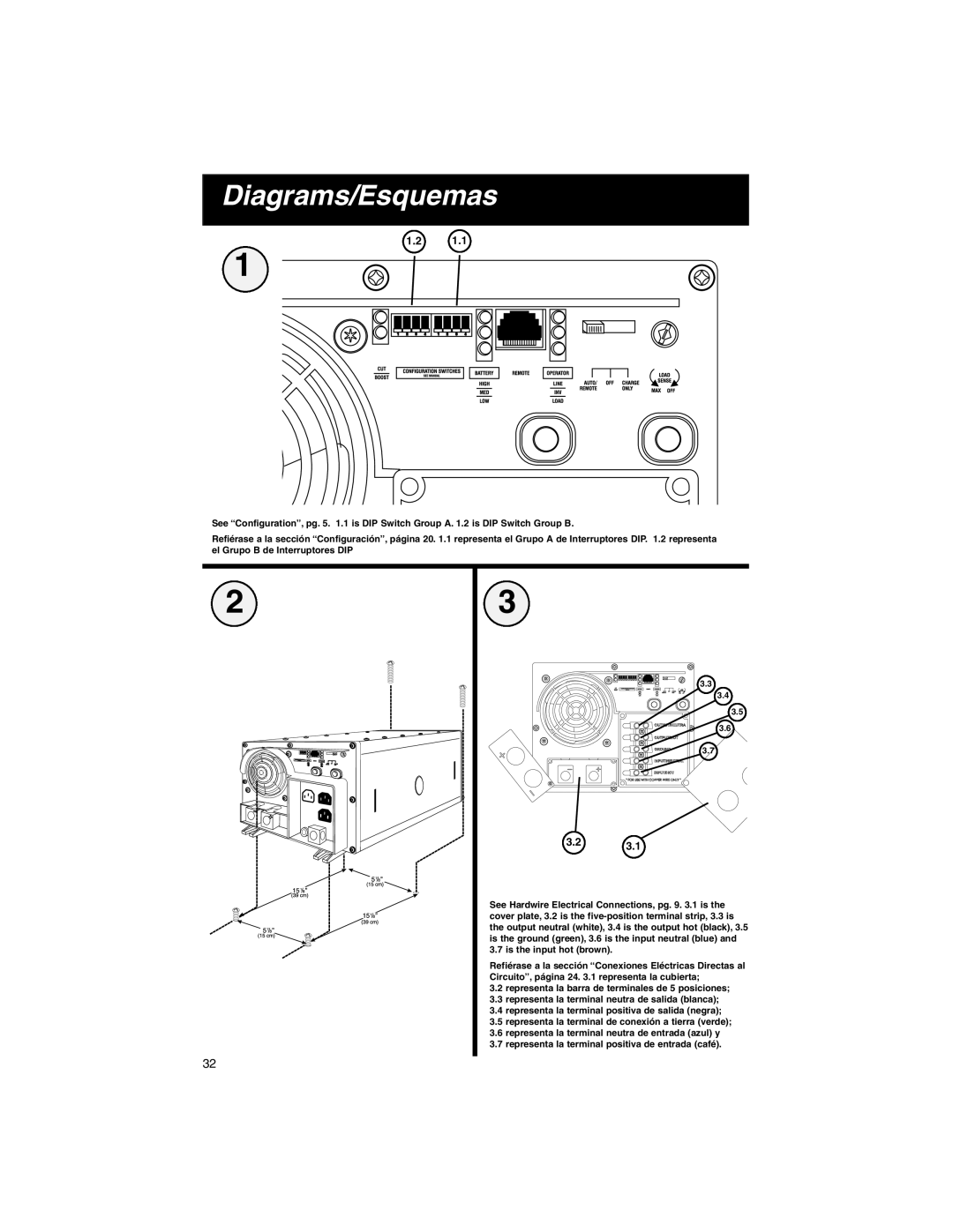
See “Configuration”, pg. 5. 1.1 is DIP Switch Group A. 1.2 is DIP Switch Group B.
Refiérase a la sección “Configuración”, página 20. 1.1 representa el Grupo A de Interruptores DIP. 1.2 representa el Grupo B de Interruptores DIP
2
3
3.3
3.4
3.5
3.6
3.7
3.23.1
See Hardwire Electrical Connections, pg. 9. 3.1 is the cover plate, 3.2 is the
Refiérase a la sección “Conexiones Eléctricas Directas al Circuito”, página 24. 3.1 representa la cubierta;
3.2representa la barra de terminales de 5 posiciones;
3.3representa la terminal neutra de salida (blanca);
3.4representa la terminal positiva de salida (negra);
3.5representa la terminal de conexión a tierra (verde);
3.6representa la terminal neutra de entrada (azul) y
3.7representa la terminal positiva de entrada (café).
32