Configuration
CONFIGURATION DIP SWITCH SETTINGS
DIP SWITCH GROUP A (All models)
BATTERY TYPE / VOLTAGE POINT
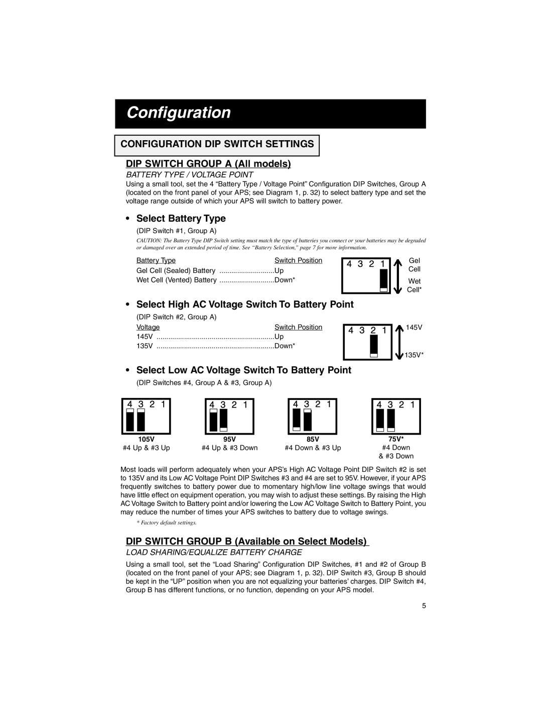
Using a small tool, set the 4 “Battery Type / Voltage Point” Configuration DIP Switches, Group A (located on the front panel of your APS; see Diagram 1, p. 32) to select battery type and set the voltage range outside of which your APS will switch to battery power.
• Select Battery Type
(DIP Switch #1, Group A)
CAUTION: The Battery Type DIP Switch setting must match the type of batteries you connect or your batteries may be degraded or damaged over an extended period of time. See “Battery Selection,” page 7 for more information.
Battery Type | Switch Position | 4 | 3 | 2 | 1 |
|
Gel Cell (Sealed) Battery | Up |
| ||||
|
|
|
|
| ||
Wet Cell (Vented) Battery | Down* |
|
|
|
|
|
|
|
|
|
|
|
|
|
|
|
|
|
|
|
|
|
|
|
|
|
|
• Select High AC Voltage Switch To Battery Point
(DIP Switch #2, Group A) |
|
|
|
|
Voltage | Switch Position |
|
|
|
4 3 2 1 | ||||
145V | Up |
|
|
|
|
|
| ||
135V | Down* |
|
|
|
|
|
|
|
|
|
|
|
|
|
|
|
|
|
|
Gel
Cell
Wet
Cell*
145V
135V*
• Select Low AC Voltage Switch To Battery Point
(DIP Switches #4, Group A & #3, Group A)
4 | 3 | 2 | 1 |
| 4 | 3 | 2 | 1 |
|
| 4 | 3 | 2 | 1 |
| ||||||
|
|
|
|
|
|
|
|
|
|
|
|
|
|
|
|
|
|
|
|
|
|
|
|
|
|
|
|
|
|
|
|
|
|
|
|
|
|
|
|
|
|
|
|
|
|
|
|
|
|
|
|
|
|
|
|
|
|
|
|
|
|
|
|
|
|
|
|
|
|
|
|
|
|
|
|
|
|
|
|
|
|
|
|
|
|
|
|
|
|
| 105V |
|
|
|
|
| 95V |
|
|
|
|
|
| 85V |
|
| |||
#4 Up & #3 Up | #4 Up & #3 Down | #4 Down & #3 Up | |||||||||||||||||||
4 3 2 1
75V*
#4 Down
& #3 Down
Most loads will perform adequately when your APS’s High AC Voltage Point DIP Switch #2 is set to 135V and its Low AC Voltage Point DIP Switches #3 and #4 are set to 95V. However, if your APS frequently switches to battery power due to momentary high/low line voltage swings that would have little effect on equipment operation, you may wish to adjust these settings. By raising the High AC Voltage Switch to Battery point and/or lowering the Low AC Voltage Switch to Battery Point, you may reduce the number of times your APS switches to battery due to voltage swings.
* Factory default settings.
DIP SWITCH GROUP B (Available on Select Models)
LOAD SHARING/EQUALIZE BATTERY CHARGE
Using a small tool, set the “Load Sharing” Configuration DIP Switches, #1 and #2 of Group B (located on the front panel of your APS; see Diagram 1, p. 32). DIP Switch #3, Group B should be kept in the “UP” position when you are not equalizing your batteries’ charges. DIP Switch #4, Group B has different functions, or no function, depending on your APS model.
5
