Configuration (continued)
Select Battery
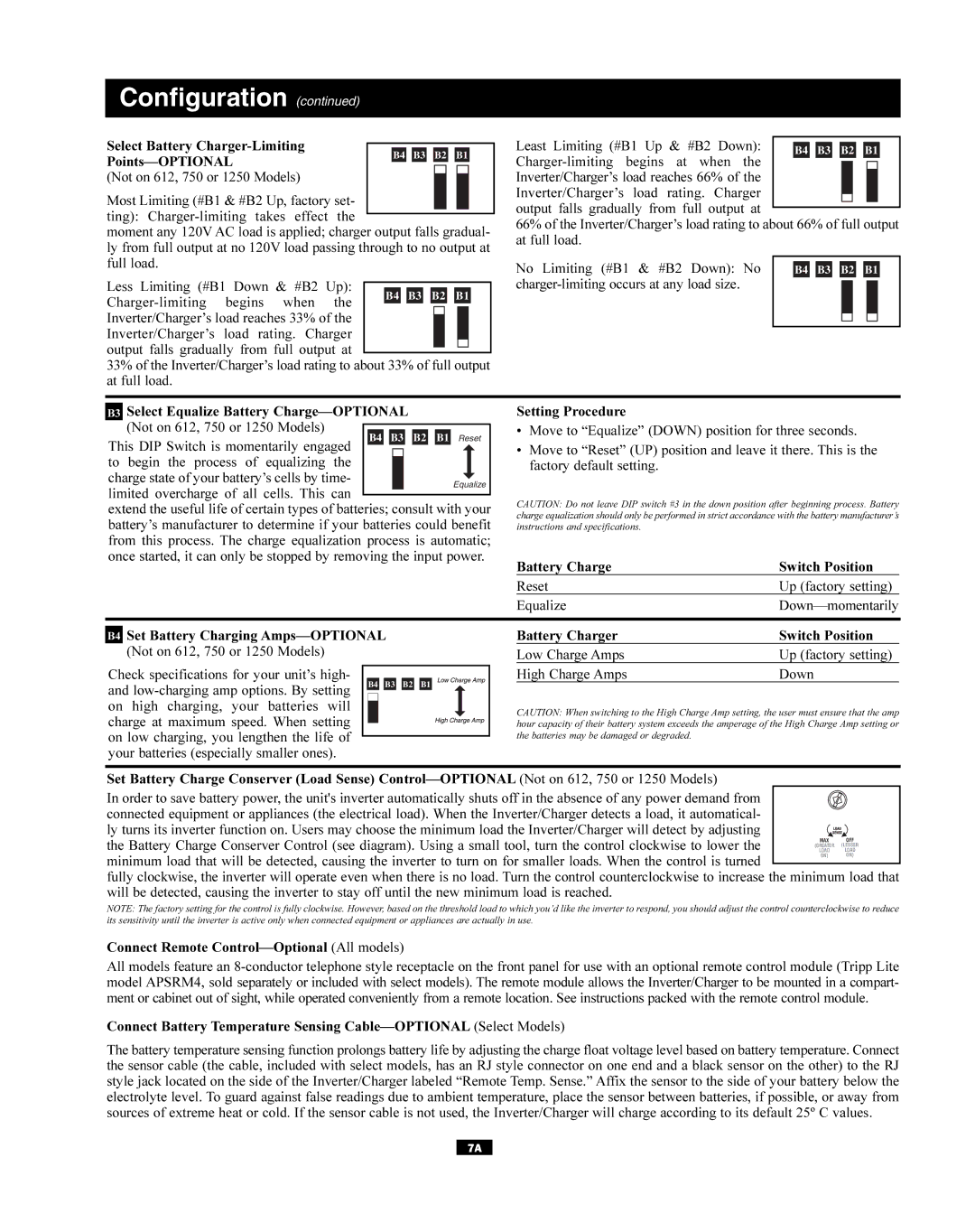
Least Limiting (#B1 Up & #B2 Down):
B4 B3 B2 B1
(Not on 612, 750 or 1250 Models)
Most Limiting (#B1 & #B2 Up, factory set- ting):
moment any 120V AC load is applied; charger output falls gradual- ly from full output at no 120V load passing through to no output at full load.
Less Limiting (#B1 Down & #B2 Up):
33% of the Inverter/Charger’s load rating to about 33% of full output at full load.
Inverter/Charger’s load reaches 66% of the Inverter/Charger’s load rating. Charger output falls gradually from full output at
66% of the Inverter/Charger’s load rating to about 66% of full output at full load.
No Limiting (#B1 & #B2 Down): No |
|
|
|
|
|
|
|
|
|
|
|
|
|
| B4 |
| B3 |
| B2 |
| B1 |
| |||||
|
|
|
|
|
|
|
|
|
|
|
|
| |
|
|
|
|
|
|
|
|
|
|
|
| ||
|
|
|
|
|
|
|
|
|
|
|
|
|
|
|
|
|
|
|
|
|
|
|
|
|
|
|
|
B3 Select Equalize Battery
This DIP Switch is momentarily engaged B4 B3 B2 B1 Reset | |||||
to begin the process of | equalizing | the |
|
| |
|
| ||||
charge state of your battery’s cells by time- |
| Equalize | |||
limited overcharge of all | cells. This | can |
|
| |
|
|
| |||
|
|
| |||
extend the useful life of certain types of batteries; consult with your battery’s manufacturer to determine if your batteries could benefit from this process. The charge equalization process is automatic; once started, it can only be stopped by removing the input power.
Setting Procedure
•Move to “Equalize” (DOWN) position for three seconds.
•Move to “Reset” (UP) position and leave it there. This is the factory default setting.
CAUTION: Do not leave DIP switch #3 in the down position after beginning process. Battery charge equalization should only be performed in strict accordance with the battery manufacturer’s instructions and specifications.
Battery Charge | Switch Position |
Reset | Up (factory setting) |
Equalize |
B4 Set Battery Charging
Check specifications for your unit’s high-
and
charge at maximum speed. When setting on low charging, you lengthen the life of your batteries (especially smaller ones).
Battery Charger | Switch Position |
Low Charge Amps | Up (factory setting) |
High Charge Amps | Down |
CAUTION: When switching to the High Charge Amp setting, the user must ensure that the amp hour capacity of their battery system exceeds the amperage of the High Charge Amp setting or the batteries may be damaged or degraded.
Set Battery Charge Conserver (Load Sense)
In order to save battery power, the unit's inverter automatically shuts off in the absence of any power demand from connected equipment or appliances (the electrical load). When the Inverter/Charger detects a load, it automatical-
ly turns its inverter function on. Users may choose the minimum load the Inverter/Charger will detect by adjusting the Battery Charge Conserver Control (see diagram). Using a small tool, turn the control clockwise to lower the
minimum load that will be detected, causing the inverter to turn on for smaller loads. When the control is turned
fully clockwise, the inverter will operate even when there is no load. Turn the control counterclockwise to increase the minimum load that will be detected, causing the inverter to stay off until the new minimum load is reached.
NOTE: The factory setting for the control is fully clockwise. However, based on the threshold load to which you’d like the inverter to respond, you should adjust the control counterclockwise to reduce its sensitivity until the inverter is active only when connected equipment or appliances are actually in use.
Connect Remote
All models feature an
Connect Battery Temperature Sensing
The battery temperature sensing function prolongs battery life by adjusting the charge float voltage level based on battery temperature. Connect the sensor cable (the cable, included with select models, has an RJ style connector on one end and a black sensor on the other) to the RJ style jack located on the side of the Inverter/Charger labeled “Remote Temp. Sense.” Affix the sensor to the side of your battery below the electrolyte level. To guard against false readings due to ambient temperature, place the sensor between batteries, if possible, or away from sources of extreme heat or cold. If the sensor cable is not used, the Inverter/Charger will charge according to its default 25º C values.
7A