AC Input/Output Connection
To avoid overloading your Inverter/Charger, be sure to match the power requirements of the equipment you plan to run at any one time (add their total watts) with the output wattage capacity of your Inverter/Charger model. When figuring the power requirements of your equipment, do not confuse “continuous” wattage with “peak” wattage ratings. Most electric motors require extra power at
• DoubleBoost™ Feature | • OverPower™ Feature |
Tripp Lite Inverter/Chargers deliver up to twice their nameplate rated wattage for up to 10 seconds,* providing the extra power needed to cold start
Tripp Lite Inverter/Chargers deliver up to 150% of their name plate rated wattage for up to 1 hour,* providing plenty of reserve power to reliably support tools and equipment longer.
* Actual duration depends on battery age, battery charge level and ambient temperature.
Connection for Models with Cords and Receptacles
With a
Warning! Consult a qualified electrician and follow all applicable electrical codes and requirements for hardwire connection. Disconnect both DC input and AC utility supply before attempting hardwiring.
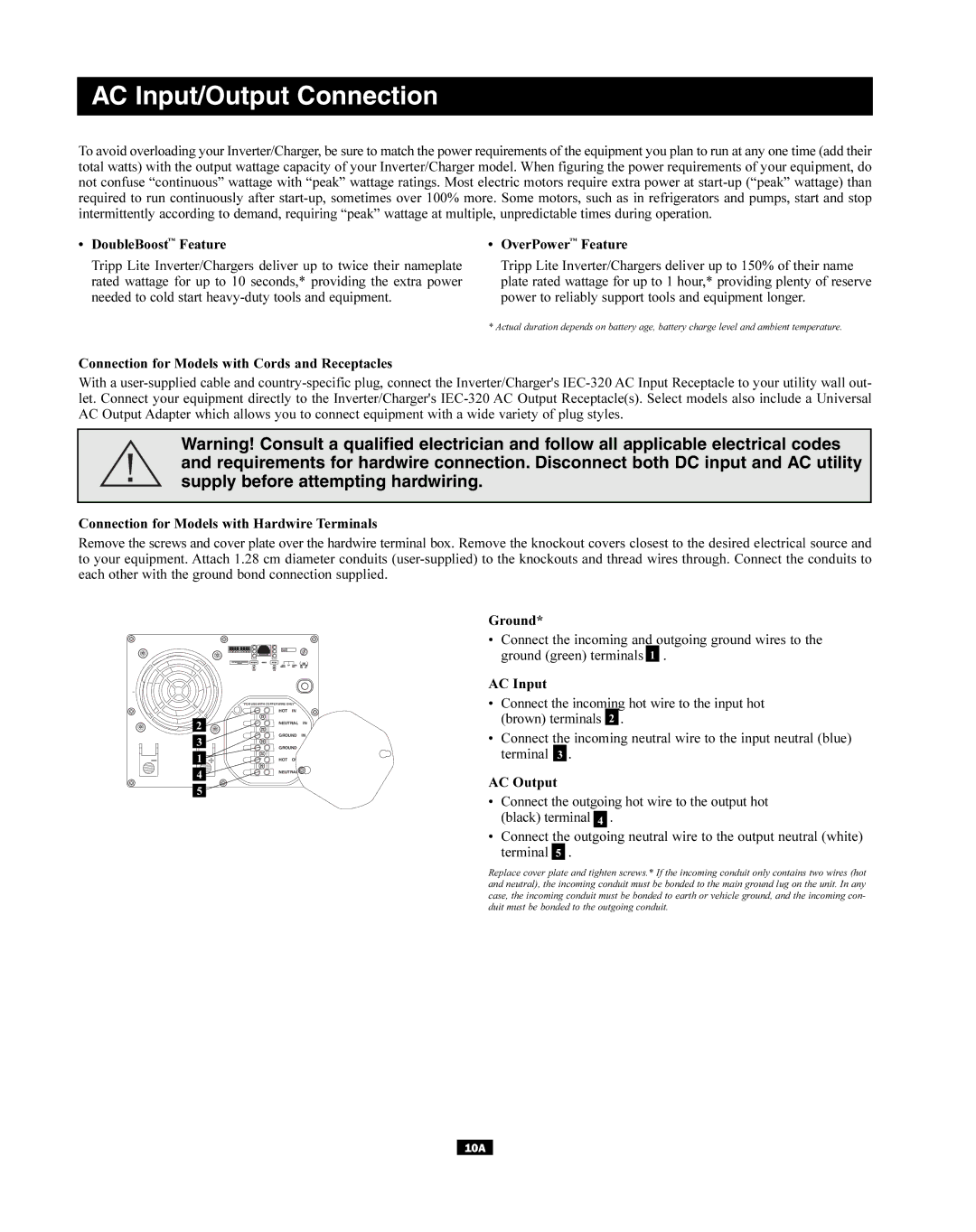
Connection for Models with Hardwire Terminals
Remove the screws and cover plate over the hardwire terminal box. Remove the knockout covers closest to the desired electrical source and to your equipment. Attach 1.28 cm diameter conduits
2
3
1
4![]()
5
“FOR USE WITH COPPER WIRE ONLY”
HOT IN
NEUTRAL IN
GROUND IN
GROUND OUT
HOT OUT
NEUTRAL OUT
Ground*
•Connect the incoming and outgoing ground wires to the ground (green) terminals 1 .
AC Input
•Connect the incoming hot wire to the input hot (brown) terminals 2 .
•Connect the incoming neutral wire to the input neutral (blue) terminal 3 .
AC Output
•Connect the outgoing hot wire to the output hot (black) terminal 4 .
•Connect the outgoing neutral wire to the output neutral (white) terminal 5 .
Replace cover plate and tighten screws.* If the incoming conduit only contains two wires (hot and neutral), the incoming conduit must be bonded to the main ground lug on the unit. In any case, the incoming conduit must be bonded to earth or vehicle ground, and the incoming con- duit must be bonded to the outgoing conduit.
10A