Configuration (continued)

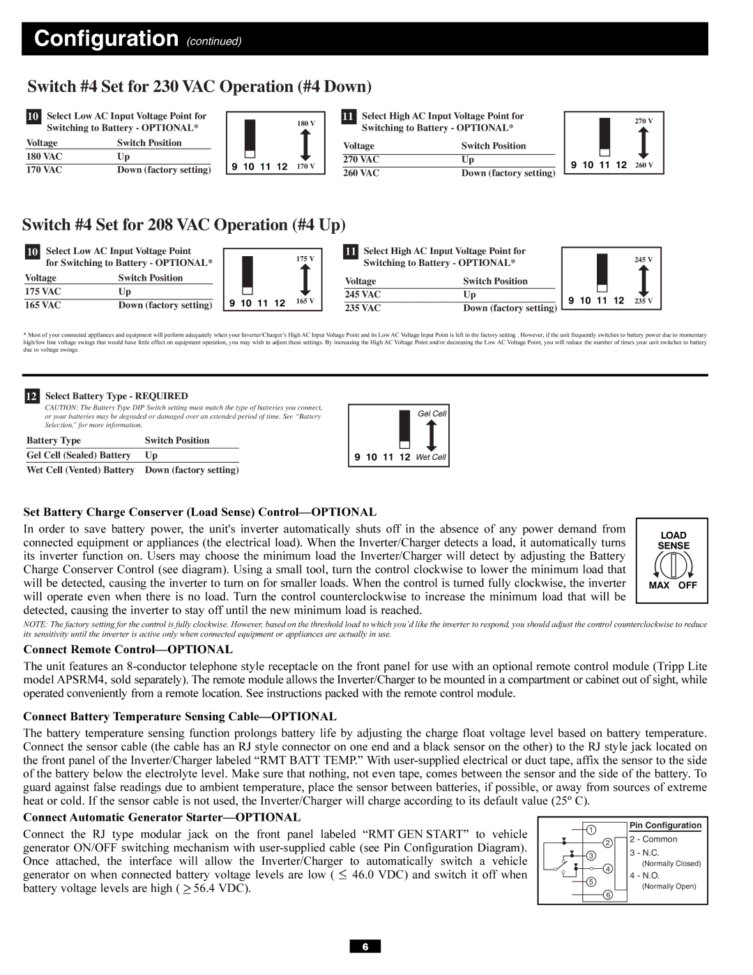
Switch #4 Set for 230 VAC Operation (#4 Down)

10

Select Low AC Input Voltage Point for


180 V


11

Select High AC Input Voltage Point for


Switching to Battery - OPTIONAL*


Switching to Battery - OPTIONAL*

Voltage

Switch Position


Voltage

Switch Position

180 VAC

Up


9 10 11 12

170 V


270 VAC

Up


170 VAC

Down (factory setting)


260 VAC

Down (factory setting)


270 V

9 10 11 12 260 V

Switch #4 Set for 208 VAC Operation (#4 Up)

10

Select Low AC Input Voltage Point


11

Select High AC Input Voltage Point for


175 V


for Switching to Battery - OPTIONAL*


Switching to Battery - OPTIONAL*

Voltage

Switch Position


Voltage

Switch Position

175 VAC

Up


9 10 11 12

165 V


245 VAC

Up


165 VAC

Down (factory setting)


235 VAC

Down (factory setting)

245 V

9 10 11 12 235 V

*Most of your connected appliances and equipment will perform adequately when your Inverter/Charger’s High AC Input Voltage Point and its Low AC Voltage Input Point is left in the factory setting . However, if the unit frequently switches to battery power due to momentary high/low line voltage swings that would have little effect on equipment operation, you may wish to adjust these settings. By increasing the High AC Voltage Point and/or decreasing the Low AC Voltage Point, you will reduce the number of times your unit switches to battery due to voltage swings.

12Select Battery Type - REQUIRED

CAUTION: The Battery Type DIP Switch setting must match the type of batteries you connect, or your batteries may be degraded or damaged over an extended period of time. See “Battery Selection,” for more information.

Battery Type

Switch Position

Gel Cell (Sealed) Battery

Up


Wet Cell (Vented) Battery

Down (factory setting)

9 10 11 12

Set Battery Charge Conserver (Load Sense) Control—OPTIONAL

In order to save battery power, the unit's inverter automatically shuts off in the absence of any power demand from connected equipment or appliances (the electrical load). When the Inverter/Charger detects a load, it automatically turns its inverter function on. Users may choose the minimum load the Inverter/Charger will detect by adjusting the Battery Charge Conserver Control (see diagram). Using a small tool, turn the control clockwise to lower the minimum load that will be detected, causing the inverter to turn on for smaller loads. When the control is turned fully clockwise, the inverter will operate even when there is no load. Turn the control counterclockwise to increase the minimum load that will be detected, causing the inverter to stay off until the new minimum load is reached.

LOAD

SENSE

MAX OFF

NOTE: The factory setting for the control is fully clockwise. However, based on the threshold load to which you’d like the inverter to respond, you should adjust the control counterclockwise to reduce its sensitivity until the inverter is active only when connected equipment or appliances are actually in use.

Connect Remote Control—OPTIONAL

The unit features an 8-conductor telephone style receptacle on the front panel for use with an optional remote control module (Tripp Lite model APSRM4, sold separately). The remote module allows the Inverter/Charger to be mounted in a compartment or cabinet out of sight, while operated conveniently from a remote location. See instructions packed with the remote control module.

Connect Battery Temperature Sensing Cable—OPTIONAL

The battery temperature sensing function prolongs battery life by adjusting the charge float voltage level based on battery temperature. Connect the sensor cable (the cable has an RJ style connector on one end and a black sensor on the other) to the RJ style jack located on the front panel of the Inverter/Charger labeled “RMT BATT TEMP.” With user-supplied electrical or duct tape, affix the sensor to the side of the battery below the electrolyte level. Make sure that nothing, not even tape, comes between the sensor and the side of the battery. To guard against false readings due to ambient temperature, place the sensor between batteries, if possible, or away from sources of extreme heat or cold. If the sensor cable is not used, the Inverter/Charger will charge according to its default value (25º C).

Connect Automatic Generator Starter—OPTIONAL

Connect the RJ type modular jack on the front panel labeled “RMT GEN START” to vehicle

1

Pin Configuration

generator ON/OFF switching mechanism with user-supplied cable (see Pin Configuration Diagram). Once attached, the interface will allow the Inverter/Charger to automatically switch a vehicle generator on when connected battery voltage levels are low ( < 46.0 VDC) and switch it off when battery voltage levels are high ( < 56.4 VDC).

22 - Common

33 - N.C.

(Normally Closed)

4

4 - N.O.

5

(Normally Open)

6

6

Page 6
Image 6
Tripp Lite APSX6048VR owner manual Switch #4 Set for 230 VAC Operation #4 Down

APSX6048VR specifications

The Tripp Lite APSX6048VR is a leading-edge power inverter designed to meet the diverse needs of users requiring reliable and efficient backup power solutions. With a robust AC output, this 6000-watt inverter provides the capability to power multiple devices and systems simultaneously, making it ideal for both residential and commercial use. Its high power capacity allows it to handle heavy loads, making it suitable for essential appliances, tools, and equipment.

One of the standout features of the APSX6048VR is its advanced pure sine wave output. Unlike modified sine wave inverters, pure sine wave inverters deliver a smooth and consistent power supply that is compatible with sensitive electronics. This ensures safe and efficient operation for devices such as computers, medical equipment, and audio/visual systems, preventing damage and prolonging their lifespan.

The inverter also includes an impressive voltage output range of 48V, which optimizes performance and maximizes efficiency. This makes it an excellent choice for solar and battery backup systems, allowing for seamless integration with renewable energy setups. The APSX6048VR supports various charging input sources, making it versatile for different installations, whether on-grid or off-grid.

Another notable characteristic of this inverter is its built-in automatic transfer switch (ATS). This feature ensures a quick transition from mains power to inverter power in the event of a power failure, providing uninterrupted power to critical loads. Additionally, the Tripp Lite APSX6048VR features multiple safety mechanisms, including over-voltage protection, under-voltage protection, and short-circuit protection, guaranteeing safe operation under varying conditions.

The inverter is designed for easy installation and user-friendly operation. It comes equipped with an LCD display that provides vital system information such as input/output voltage, load capacity, and battery status. This real-time feedback allows users to monitor their power usage effectively.

With durable construction and a compact design, the Tripp Lite APSX6048VR is both portable and durable, making it a reliable choice for temporary setups or permanent installations. It’s an ideal power solution for anyone seeking a reliable inverter that combines high performance with advanced technology, ensuring that devices remain powered in any situation.