Switch Modes |
|
|
|
|
|
|
|
| Resetting Your Inverter to Restore | |
Switch between the following operating modes as appropriate to | AC Power | |||||||||
your situation: |
|
|
|
|
|
|
|
| Your Inverter may cease supplying AC power in order to protect | |
“ON”: Switch to this setting to provide connected |
|
|
|
|
|
|
|
|
| |
|
|
|
|
|
|
|
|
| itself from overload or to protect your electrical system. To restore | |
equipment with AC power. |
|
|
|
|
|
|
|
|
| |
|
|
|
|
|
|
|
|
| normal functioning: | |
|
|
|
|
|
|
|
|
|
| |
|
|
|
|
|
|
|
| |||
|
| REMOTE | OFF | ON | Low Battery Shutdown Reset: Set operating mode switch to | |||||
|
|
|
|
|
|
|
|
|
| |
|
|
|
|
|
|
|
|
|
| |
“OFF”: Switch to this setting to shut down the Inverter |
|
|
|
|
|
|
|
| “OFF” and run vehicle engine to recharge battery. When battery is | |
|
|
|
|
|
|
|
| adequately charged, switch operating mode switch back to either | ||
completely, preventing it from drawing power from |
|
|
|
|
|
|
|
| ||
|
|
|
|
|
|
|
| “REMOTE” or “ON.” | ||
the batteries. Use this switch to automatically reset |
|
|
|
|
|
|
|
| ||
|
|
|
|
|
|
|
| Overload Shutdown Reset: Set operating mode switch to “OFF” | ||
the unit if it shuts down due to low battery or overload. |
|
|
|
|
|
|
|
| ||
REMOTE | OFF | ON | ||||||||
Use an optional remote control module (Tripp Lite model APSRM4, | and remove some of the connected electrical load (ie: turn off some | |||||||||
sold separately or included with PV3000HF models) to reset unit | of the AC devices drawing power which may have caused the over- | |||||||||
due to overload only. |
|
|
|
|
|
|
|
| load of the unit). Wait one minute, then switch operating mode | |
|
|
|
|
|
|
|
| switch back to either “REMOTE” or “ON.” | ||
|
|
|
|
|
|
|
|
|
| |
“REMOTE”: Switch to this setting to remotely |
|
|
|
|
|
|
|
| Output Circuit Breaker Reset (Select Models): Alternatively, | |
|
|
|
|
|
|
|
| |||
monitor and control the Inverter with the use of an |
|
|
|
|
|
|
|
| ||
|
|
|
|
|
|
|
| check output circuit breaker(s) on the unit's front panel. If tripped, | ||
optional remote module. See remote module’s |
|
|
|
|
|
|
|
| ||
|
|
|
|
|
|
|
| remove some of the electrical load, then wait one minute to allow | ||
|
|
|
|
|
|
|
| |||
owner’s manual for operating instructions. | REMOTE | OFF | ON | |||||||
|
|
|
|
|
|
|
| components to cool before resetting the circuit breaker. See | ||
|
|
|
|
|
|
|
| |||
|
|
|
|
|
|
|
|
|
| |
|
|
|
|
|
|
|
|
|
| Troubleshooting for other possible reasons AC output may be absent. |
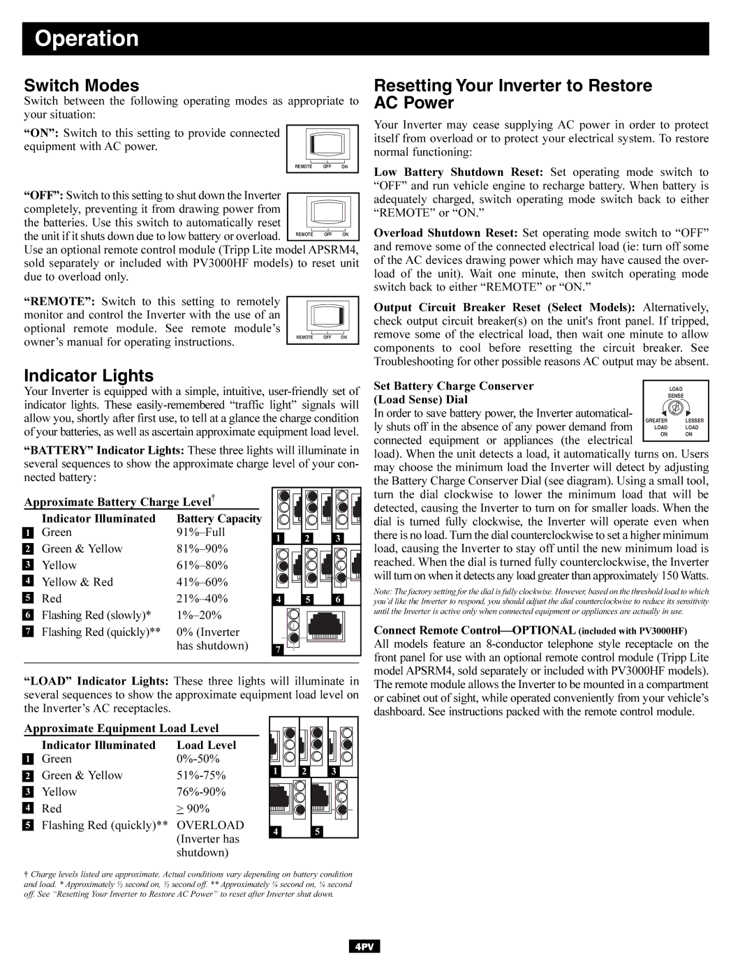
Your Inverter is equipped with a simple, intuitive, | Set Battery Charge Conserver |
| LOAD | |||||
(Load Sense) Dial |
| SENSE | ||||||
indicator lights. These |
|
| ||||||
allow you, shortly after first use, to tell at a glance the charge condition | In order to save battery power, the Inverter automatical- | GREATER | LESSER | |||||
of your batteries, as well as ascertain approximate equipment load level. | ly shuts off in the absence of any power demand from | LOAD | LOAD | |||||
ON | ON | |||||||
“BATTERY” Indicator Lights: These three lights will illuminate in | connected equipment or appliances (the electrical |
|
| |||||
load). When the unit detects a load, it automatically turns on. Users | ||||||||
several sequences to show the approximate charge level of your con- | may choose the minimum load the Inverter will detect by adjusting | |||||||
nected battery: |
|
|
|
| the Battery Charge Conserver Dial (see diagram). Using a small tool, | |||
|
|
|
|
|
| |||
Approximate Battery Charge Level† |
|
|
| turn the dial clockwise to lower the minimum load that will be | ||||
| Indicator Illuminated | Battery Capacity |
|
|
| detected, causing the Inverter to turn on for smaller loads. When the | ||
|
|
|
| dial is turned fully clockwise, the Inverter will operate even when | ||||
1 | Green | 1 | 2 | 3 | there is no load. Turn the dial counterclockwise to set a higher minimum | |||
|
|
| ||||||
2 | Green & Yellow |
|
|
| load, causing the Inverter to stay off until the new minimum load is | |||
3 | Yellow |
|
|
| reached. When the dial is turned fully counterclockwise, the Inverter | |||
4 | Yellow & Red |
|
|
| will turn on when it detects any load greater than approximately 150 Watts. | |||
|
|
| Note: The factory setting for the dial is fully clockwise. However, based on the threshold load to which | |||||
5 | Red |
| 4 |
| 6 | |||
5 | you’d like the Inverter to respond, you should adjust the dial counterclockwise to reduce its sensitivity | |||||||
6 | Flashing Red (slowly)* |
|
|
|
| until the Inverter is active only when connected equipment or appliances are actually in use. | ||
|
|
|
|
|
| |||
| 7 | Flashing Red (quickly)** 0% (Inverter |
|
|
|
|
| Connect Remote |
|
|
|
|
|
| |||
|
| has shutdown) |
|
|
|
|
| All models feature an |
| 7 |
|
|
|
| |||
|
|
|
|
|
|
| front panel for use with an optional remote control module (Tripp Lite | |
|
|
|
|
|
|
|
| |
| “LOAD” Indicator Lights: These three lights will illuminate in | model APSRM4, sold separately or included with PV3000HF models). | ||||||
| The remote module allows the Inverter to be mounted in a compartment | |||||||
| several sequences to show the approximate equipment load level on | or cabinet out of sight, while operated conveniently from your vehicle’s | ||||||
| the Inverter’s AC receptacles. |
|
|
|
|
| dashboard. See instructions packed with the remote control module. | |
|
|
|
|
|
|
|
| |
Approximate Equipment Load Level |
|
|
| ||
| Indicator Illuminated | Load Level |
|
|
|
1 | Green |
|
|
| |
2 | Green & Yellow | 1 | 2 | 3 | |
|
|
| |||
3 | Yellow |
|
|
| |
4 | Red | > 90% |
|
|
|
5 | Flashing Red (quickly)** | OVERLOAD | 4 |
| 5 |
|
| (Inverter has |
| ||
|
|
|
|
| |
|
| shutdown) |
|
|
|
† Charge levels listed are approximate. Actual conditions vary depending on battery condition | |||||
and load. * Approximately ½ second on, ½ second off. ** Approximately ¼ second on, ¼ second | |||||
off. See “Resetting Your Inverter to Restore AC Power” to reset after Inverter shut down. | |||||
4PV