C3 = Reset at Power-up
Auto = Automatic reset
nAn = Manual reset
C4 = Reset Memory
0= The reset condition will be saved (at next power up it will be reactivated)
1= The reset condition will be lost in case of power down
C5 = Time Constant for Filter on Measured Value for Reset Action
Range: From 0 (filter OFF) to 8 seconds
Note: First order filter with selected time Constant.
P1 = Alarm Function (Skipped if option not available) nonE = Not provided
AL.P = Process alarm AL.b = Band alarm AL.d = Deviation alarm
When C1 = Hi.Lo, “AL.b” and “AL.d” are not available.
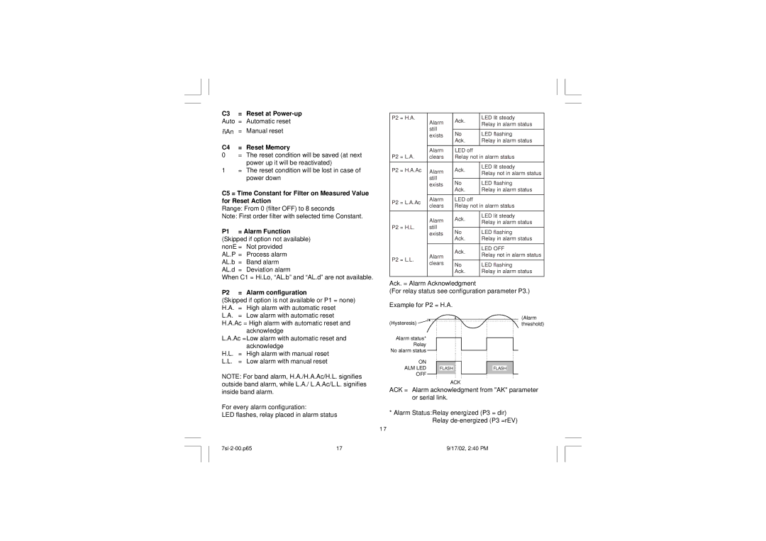
P2 = Alarm configuration
(Skipped if option is not available or P1 = none) H.A. = High alarm with automatic reset
L.A. = Low alarm with automatic reset H.A.Ac = High alarm with automatic reset and
acknowledge
P2 = H.A. | Alarm | Ack. | LED lit steady | |
| Relay in alarm status | |||
|
| |||
| still |
|
| |
| No | LED flashing | ||
| exists | |||
|
| Ack. | Relay in alarm status | |
|
|
|
| |
| Alarm | LED off |
| |
P2 = L.A. | clears | Relay not in alarm status | ||
|
|
|
| |
P2 = H.A.Ac | Alarm | Ack. | LED lit steady | |
Relay not in alarm status | ||||
|
| |||
| still |
|
| |
| No | LED flashing | ||
| exists | |||
|
| Ack. | Relay in alarm status | |
|
|
|
| |
P2 = L.A.Ac | Alarm | LED off |
| |
clears | Relay not in alarm status | |||
| ||||
|
|
|
| |
| Alarm | Ack. | LED lit steady | |
| Relay in alarm status | |||
|
| |||
P2 = H.L. | still |
|
| |
No | LED flashing | |||
| exists | |||
|
| Ack. | Relay in alarm status | |
|
|
|
| |
|
| Ack. | LED OFF | |
| Alarm | Relay not in alarm status | ||
P2 = L.L. |
| |||
|
| |||
clears | No | LED flashing | ||
| ||||
|
| |||
|
| Ack. | Relay in alarm status | |
|
|
|
| |
Ack. = Alarm Acknowledgment
(For relay status see configuration parameter P3.)
Example for P2 = H.A.
(Alarm
(Hysteresis) ![]() threshold)
threshold)
L.A.Ac =Low alarm with automatic reset and acknowledge
H.L. = High alarm with manual reset L.L. = Low alarm with manual reset
NOTE: For band alarm, H.A./H.A.Ac/H.L. signifies outside band alarm, while L.A./ L.A.Ac/L.L. signifies
Alarm status* Relay No alarm status
ON
ALM LED
OFF
FLASH
ACK
FLASH
inside band alarm.
For every alarm configuration:
LED flashes, relay placed in alarm status
1 7
ACK = Alarm acknowledgment from "AK" parameter or serial link.
*Alarm Status:Relay energized (P3 = dir) Relay
17 | 9/17/02, 2:40 PM |
