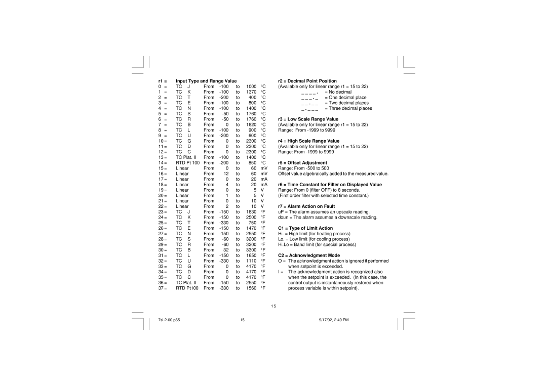
r1 = | Input Type and Range Value |
|
| r2 = Decimal Point Position | |||||
0 | = | TC | J | From | to | 1000 | °C | (Available only for linear range r1 = 15 to 22) | |
1 | = | TC | K | From | to | 1370 | °C | _ _ _ _ . = No decimal | |
2 | = | TC | T | From | to | 400 | °C | _ _ _ . _ = One decimal place | |
3 | = | TC | E | From | to | 800 | °C | _ _ . _ _ = Two decimal places | |
4 | = | TC | N | From | to | 1400 | °C | _ . _ _ _ = Three decimal places | |
5 | = | TC | S | From | to | 1760 | °C |
| |
6 | = | TC | R | From | to | 1760 | °C | r3 = Low Scale Range Value | |
7 | = | TC | B | From | 0 | to | 1820 | °C | (Available only for linear range r1 = 15 to 22) |
8 | = | TC | L | From | to | 900 | °C | Range: From | |
9 | = | TC | U | From | to | 600 | °C |
| |
10 | = | TC | G | From | 0 | to | 2300 | °C | r4 = High Scale Range Value |
11 | = | TC | D | From | 0 | to | 2300 | °C | (Available only for linear range r1 = 15 to 22) |
12 | = | TC | C | From | 0 | to | 2300 | °C | Range: From |
13 | = | TC Plat. II | From | to | 1400 | °C |
| ||
14 | = | RTD Pt 100 | From | to | 850 | °C | r5 = Offset Adjustment | ||
15 | = | Linear | From | 0 | to | 60 | mV | Range: From | |
16 | = | Linear | From | 12 | to | 60 | mV | Offset value algebraically added to the measured value. | |
17 | = | Linear | From | 0 | to | 20 | mA |
| |
18 | = | Linear | From | 4 | to | 20 | mA | r6 = Time Constant for Filter on Displayed Value | |
19 | = | Linear | From | 0 | to | 5 | V | Range: From 0 (filter OFF) to 8 seconds. | |
20 | = | Linear | From | 1 | to | 5 | V | (First order filter with selected time constant.) | |
21 | = | Linear | From | 0 | to | 10 | V |
| |
22 | = | Linear | From | 2 | to | 10 | V | r7 = Alarm Action on Fault | |
23 | = | TC | J | From | to | 1830 | °F | uP = The alarm assumes an upscale reading. | |
24 | = | TC | K | From | to | 2500 | °F | doun = The alarm assumes a downscale reading. | |
25 | = | TC | T | From | to | 750 | °F |
| |
26 | = | TC | E | From | to | 1470 | °F | C1 = Type of Limit Action | |
27 | = | TC | N | From | to | 2550 | °F | Hi. = High limit (for heating process) | |
28 | = | TC | S | From | to | 3200 | °F | Lo. = Low limit (for cooling process) | |
29 | = | TC | R | From | to | 3200 | °F | Hi.Lo = Band limit (for special process) | |
30 | = | TC | B | From | 32 | to | 3300 | °F |
|
31 | = | TC | L | From | to | 1650 | °F | C2 = Acknowledgment Mode | |
32 | = | TC | U | From | to | 1110 | °F | O = The acknowledgment action is ignored if performed | |
33 | = | TC | G | From | 0 | to | 4170 | °F | when setpoint is exceeded. |
34 | = | TC | D | From | 0 | to | 4170 | °F | I = The acknowledgment action is recognized also |
35 | = | TC | C | From | 0 | to | 4170 | °F | when the setpoint is exceeded. (In this case, the |
36 | = | TC Plat. II | From | to | 2550 | °F | control output is instantaneously restored when | ||
37 | = | RTD Pt100 | From | to | 1560 | °F | process variable is within setpoint). | ||
|
|
|
|
|
|
|
|
| 1 5 |
15 | 9/17/02, 2:40 PM |