Control Output Function
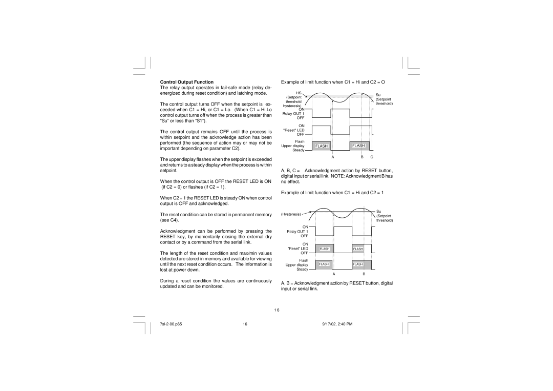
Example of limit function when C1 = Hi and C2 = O
The relay output operates in
The control output turns OFF when the setpoint is ex- ceeded when C1 = Hi, or C1 = Lo. (When C1 = Hi.Lo control output turns off when the process is greater than “Su” or less than “S1”).
The control output remains OFF until the process is within setpoint and the acknowledge action has been performed (the sequence of action may or may not be important depending on parameter C2).
The upper display flashes when the setpoint is exceeded and returns to a steady display when the process is within
HS |
|
(Setpoint |
|
threshold |
|
hysteresis) |
|
ON |
|
Relay OUT 1 |
|
OFF |
|
ON |
|
"Reset" LED |
|
OFF |
|
Flash |
|
Upper display | FLASH |
Steady |
|
| A |
Su (Setpoint threshold)
FLASH
B C
setpoint.
When the control output is OFF the RESET LED is ON (if C2 = 0) or flashes (if C2 = 1).
When C2 = 1 the RESET LED is steady ON when control output is OFF and acknowledged.
A, B, C = Acknowledgment action by RESET button, digital input or serial link. NOTE: Acknowledgment B has no effect.
Example of limit function when C1 = Hi and C2 = 1
The reset condition can be stored in permanent memory (see C4).
Acknowledgment can be performed by pressing the RESET key, by momentarily closing the external dry contact or by a command from the serial link.
The length of the reset condition and max/min values detected are stored in memory and available for viewing until the next reset condition occurs. The information is lost at power down.
(Hysteresis) ![]()
ON
Relay OUT 1
OFF
ON "Reset" LED OFF
Flash Upper display Steady
FLASH
FLASH
A
Su (Setpoint threshold)
FLASH
FLASH
B
During a reset condition the values are continuously updated and can be monitored.
A, B = Acknowledgment action by RESET button, digital input or serial link.
1 6
16 | 9/17/02, 2:40 PM |