CALIBRATION PROCEDURE
Calibration parameters are logically divided into groups of two parameters each – initial scale value and final scale value. A calibration check is provided after entering the values of each group. It is also possible to perform a calibration check without making an entry: press the FUNC button twice when “OFF” is displayed. The instru- ment goes directly to the group check.
Before beginning calibration, be sure the internal DIP switch V101 is open.
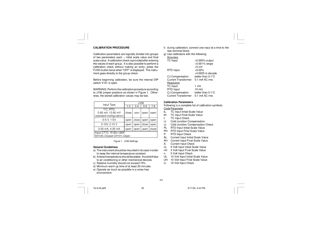
WARNING: Perform the calibration procedure according to J106 jumper positions as shown in Figure 1. Other- wise, the stored calibration values may be lost.
Input Type |
| J106 |
| |
| ||||
T/C, RTD, |
|
|
|
|
close | open | open | open | |
(standard configuration) |
|
|
|
|
open | close | open | open | |
|
|
|
|
|
open | open | close | open | |
|
|
|
|
|
open | open | open | close | |
|
|
|
|
|
Input CTTC R192=180K |
|
|
| |
SH120=Closed CH101=Open |
|
|
| |
Figure 1. | J106 Settings |
|
| |
General Guidelines
a)The instrument should be mounted in its case in order to keep the internal temperature constant.
b)Ambient temperature should be stable. Avoid drift due to air conditioning or other mechanical devices.
c)Relative humidity should not exceed 70%.
d)Minimum warm up time of at least 20 minutes.
e)Operate as much as possible in a noise free environment.
f)during calibration, connect one input at a time to the rear terminal block.
g)Use calibrators with the following:
Accuracy
TC Input:
RTD Input:
CJ Compensation:
Current Transformer:
Resolution
TC Input:
RTD Input:
CJ Compensation:
Current Transformer:
Calibration Parameters
Following is a complete list of calibration symbols: Code Parameter
tL | TC Input Initial Scale Value |
tH | TC Input Final Scale Value |
t.TC Input Check
rJ | Cold Junction Compensation |
rJ. | Cold Junction Compensation Check |
PL | RTD Input Initial Scale Value |
PH | RTD Input Final Scale Value |
P.RTD Input Check
AL | Current Input Initial Scale Value |
AH | Current Input Final Scale Value |
A.Current Input Check
nL | 5 | Volt Input Initial Scale Value |
nH | 5 | Volt Input Final Scale Value |
n.5 Volt Input Check
UL | 10 | Volt Input Initial Scale Value |
UH | 10 | Volt Input Final Scale Value |
U.10 Volt Input Check
3 0
30 | 9/17/02, 2:44 PM |