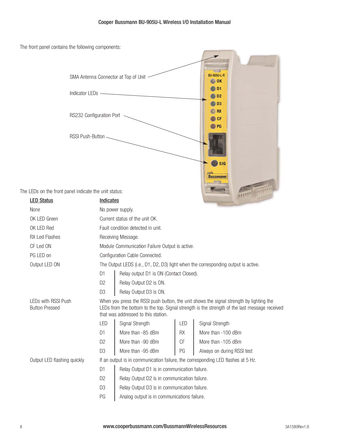
BU-905U-L specifications
The Cooper Bussmann BU-905U-L is a critical component known for its reliable performance in various electrical applications. This fuse is designed to protect circuits from overloads and short circuits, ensuring the safety and integrity of electrical systems in residential, commercial, and industrial settings.One of the main features of the BU-905U-L is its high breaking capacity, which allows it to effectively interrupt excessive current flow without damaging connected devices. This feature makes it suitable for use in demanding environments where reliable protection is crucial. The fuse is built to handle transient events, making it ideal for applications subject to short bursts of high current.
The fuse utilizes advanced materials and technologies to enhance its durability and efficiency. Its construction includes a robust, non-combustible housing that offers excellent thermal resistance and mechanical strength. This ensures the fuse can withstand harsh operating conditions while maintaining its protective capabilities. The BU-905U-L is also designed for quick and easy replacement, minimizing downtime during maintenance.
Another significant characteristic of the BU-905U-L is its thoughtful design for ease of installation. It features a standard size that is compatible with various fuse holders, allowing for a seamless integration into existing systems. Additionally, the fuse is marked with clear ratings, enabling users to quickly identify its specifications for proper selection and installation.
In terms of electrical ratings, the BU-905U-L is designed to handle a specific voltage and current, which makes it suitable for a diverse range of applications, including motor protection, lighting circuits, and power distribution systems. These fuses come with various current ratings, offering flexibility for different load requirements.
Moreover, built on a commitment to safety and quality, Cooper Bussmann ensures that the BU-905U-L meets stringent industry standards and certifications. This not only guarantees the reliability of the product but also provides peace of mind to users knowing that their electrical systems are well protected.
In summary, the Cooper Bussmann BU-905U-L fuse combines high performance, advanced material technology, and user-friendly characteristics, making it an invaluable component in any electrical system. Whether for industrial machinery or everyday electrical circuits, this fuse provides essential protection, ensuring safety and reliability in energy management.

