Manuals
/
Tripp Lite
/
Computer Equipment
/
Power Supply
Tripp Lite
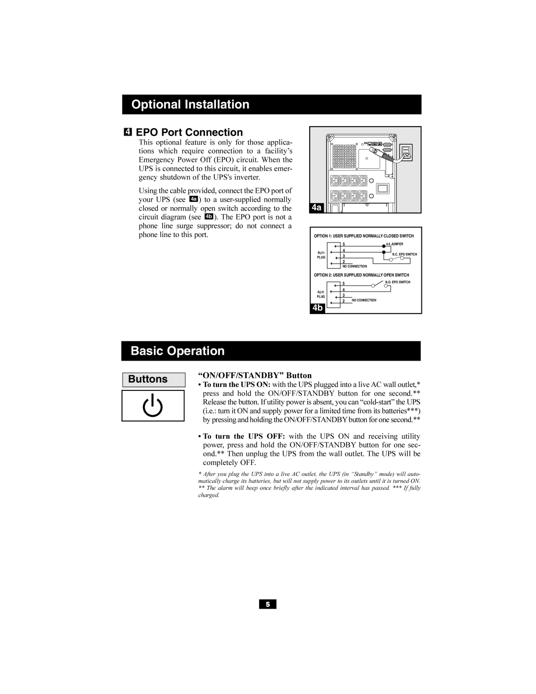
SMARTINT2200VS Optional Installation, Basic Operation, EPO Port Connection, Buttons
Models:
SMARTINT2200VS
SMARTINT3000VS
1
5
11
11
Download
11 pages
56.75 Kb
1
2
3
4
5
6
7
8
Specifications
Indicator Lights Front Panel
Battery Warnings
Service
Other UPS Features Back Panel
Page 5
Image 5
Page 4
Page 6
Page 5
Image 5
Page 4
Page 6
Contents
Quick Installation
Important Safety Instructions
Optional Installation
Storage & Service
SAVE THESE INSTRUCTIONS
Battery Warnings
UPS Location Warnings
UPS Connection Warnings
Turn the UPS ON
RS-232 Serial Communications
External Battery Connection
USB Communications
“ON/OFF/STANDBY” Button
EPO Port Connection
Buttons
Indicator Lights Front Panel
Basic Operation continued
Basic Operation continued
Other UPS Features Back Panel
NORM DELAY
Charge Rate Setting when External Batteries are not connected
Charge Rate Setting when External Batteries are connected
Storage
Service
200404080 93-2245EN
1111 W. 35th Street, Chicago, IL 60609 USA
773.869.1234 USA 773.869.1212 International
Top
Page
Image
Contents