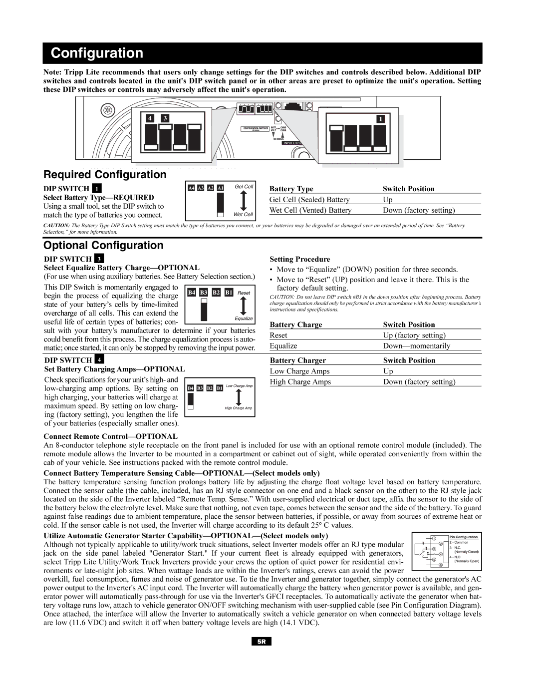
Configuration
Note: Tripp Lite recommends that users only change settings for the DIP switches and controls described below. Additional DIP switches and controls located in the unit's DIP switch panel or in other areas are preset to optimize the unit's operation. Setting these DIP switches or controls may adversely affect the unit's operation.
Required Configuration
DIP SWITCH 1
Select Battery
A4 A3 A2 A1
Battery Type | Switch Position |
Gel Cell (Sealed) Battery | Up |
Wet Cell (Vented) Battery | Down (factory setting) |
CAUTION: The Battery Type DIP Switch setting must match the type of batteries you connect, or your batteries may be degraded or damaged over an extended period of time. See “Battery Selection,” for more information.
Optional Configuration
DIP SWITCH | 3 |
| Setting Procedure |
| ||||||||||||||||||||||
Select Equalize Battery | • | Move to “Equalize” (DOWN) position for three seconds. | ||||||||||||||||||||||||
(For use when using auxiliary batteries. See Battery Selection section.) | • | Move to “Reset” (UP) position and leave it there. This is the | ||||||||||||||||||||||||
|
|
|
|
|
|
|
|
|
|
|
|
|
|
|
|
|
|
|
|
|
|
| ||||
This DIP Switch is momentarily engaged to |
|
|
|
|
|
|
|
|
|
|
| factory default setting. |
| |||||||||||||
|
|
|
|
|
|
|
|
|
|
|
|
|
|
|
|
| ||||||||||
|
|
|
|
|
| |||||||||||||||||||||
begin the process of equalizing the charge |
|
|
|
|
|
|
|
|
|
|
| CAUTION: Do not leave DIP switch #B3 in the down position after beginning process. Battery | ||||||||||||||
|
|
|
|
|
| |||||||||||||||||||||
state of your battery’s cells by |
|
|
|
|
|
|
|
|
|
|
|
|
|
|
|
|
|
| charge equalization should only be performed in strict accordance with the battery manufacturer’s | |||||||
|
|
|
|
|
|
|
|
|
|
|
|
|
|
|
|
|
| |||||||||
|
|
|
|
|
|
|
|
|
| instructions and specifications. |
| |||||||||||||||
overcharge of all cells. This can extend the |
|
|
|
|
|
|
|
|
|
|
|
|
|
|
|
|
|
|
| |||||||
|
|
|
|
|
|
|
|
|
|
|
|
|
|
|
|
| ||||||||||
useful life of certain types of batteries; con- |
|
|
|
|
|
|
|
|
|
| Battery Charge | Switch Position | ||||||||||||||
| ||||||||||||||||||||||||||
sult with your battery’s manufacturer to determine if your batteries | ||||||||||||||||||||||||||
Reset | Up (factory setting) | |||||||||||||||||||||||||
could benefit from this process. The charge equalization process is auto- | ||||||||||||||||||||||||||
Equalize | ||||||||||||||||||||||||||
matic; once started, it can only be stopped by removing the input power. | ||||||||||||||||||||||||||
|
|
|
|
| ||||||||||||||||||||||
DIP SWITCH | 4 |
| Battery Charger | Switch Position | ||||||||||||||||||||||
Set Battery Charging |
|
|
| |||||||||||||||||||||||
Low Charge Amps | Up | |||||||||||||||||||||||||
|
|
|
|
|
|
|
|
|
|
|
|
|
|
|
|
|
|
|
|
|
|
| ||||
Check specifications for your unit’s high- and |
|
|
|
|
|
|
|
|
|
|
|
|
|
| High Charge Amps | Down (factory setting) | ||||||||||
|
|
|
|
|
|
|
|
|
|
|
|
| ||||||||||||||
|
|
|
|
|
|
|
|
|
|
|
|
|
|
|
|
|
|
| ||||||||
|
|
|
|
|
|
|
|
|
|
|
|
|
|
|
|
|
|
|
|
|
| |||||
|
|
| ||||||||||||||||||||||||
high charging, your batteries will charge at |
|
|
|
|
|
|
|
|
|
|
|
|
|
|
|
|
|
|
|
|
|
| ||||
maximum speed. By setting on low charg- |
|
|
|
|
|
|
|
|
|
|
|
|
|
|
|
|
|
|
|
|
|
| ||||
|
|
|
|
|
|
|
|
|
|
|
|
|
|
|
|
|
|
|
| |||||||
ing (factory setting), you lengthen the life |
|
|
|
|
|
|
|
|
|
|
|
|
|
|
|
|
| |||||||||
of your batteries (especially smaller ones). |
|
|
| |||||||||||||||||||||||
Connect Remote
An
Connect Battery Temperature Sensing
The battery temperature sensing function prolongs battery life by adjusting the charge float voltage level based on battery temperature. Connect the sensor cable (the cable, included, has an RJ style connector on one end and a black sensor on the other) to the RJ style jack located on the side of the Inverter labeled “Remote Temp. Sense.” With
Utilize Automatic Generator Starter ![]()
![]()
![]()
![]()
![]()
![]()
![]()
![]()
![]()
![]()
![]()
![]()
![]()
![]()
![]()
![]() Although not typically applicable to utility/work truck situations, select Inverter models offer an RJ type modular
Although not typically applicable to utility/work truck situations, select Inverter models offer an RJ type modular ![]()
![]()
![]()
![]()
![]()
![]()
![]()
![]()
![]()
![]()
![]() jack on the side panel labeled "Generator Start." If your current fleet is already equipped with generators,
jack on the side panel labeled "Generator Start." If your current fleet is already equipped with generators, ![]()
![]()
![]()
![]()
![]()
![]()
![]()
![]()
![]()
![]()
![]()
![]()
![]()
![]()
![]()
![]()
![]()
![]() select Tripp Lite Utility/Work Truck Inverters provide your crews the option of quiet power for residential envi-
select Tripp Lite Utility/Work Truck Inverters provide your crews the option of quiet power for residential envi- ![]()
![]()
![]()
![]()
![]()
![]()
![]()
![]()
![]()
![]()
![]()
![]()
![]()
![]()
![]()
![]()
![]() ronments or
ronments or ![]() overkill, fuel consumption, fumes and noise of generator use. To tie the Inverter and generator together, simply connect the generator's AC power output to the Inverter's AC input cord. The Inverter will automatically charge the battery when generator power is available, and gen- erator power will automatically
overkill, fuel consumption, fumes and noise of generator use. To tie the Inverter and generator together, simply connect the generator's AC power output to the Inverter's AC input cord. The Inverter will automatically charge the battery when generator power is available, and gen- erator power will automatically
5R