Removing The Tractor From Storage
•Check the engine oil.
•Fully charge the battery and inflate the tires to the recommended pressure.
•If drained before storing, fill the fuel tank with clean, fresh gasoline.
•Add clean, fresh fuel.
•Start the engine and allow to idle for a few minutes to ensure engine is operating properly.
•Drive the tractor without a load to make certain all the tractor systems are functioning properly.
Adjustments
WARNING! Shut the engine off, remove the ignition key and engage the parking brake before making adjustments. Protect your hands by using heavy gloves when handling the blades.
Adjusting the Operators Seat
•To adjust the position of the seat, move and hold the seat adjustment lever toward the left. Slide the seat forward or rearward to the desired position; then release the adjustment lever. Make sure seat is locked into position before operating the tractor. See Figure
Seat
Move Lever to Left
![]() Adjustment
Adjustment
Lever
Figure
Adjusting RH & LH Drive Control Levers
The RH and LH drive control levers can be adjusted up or down and
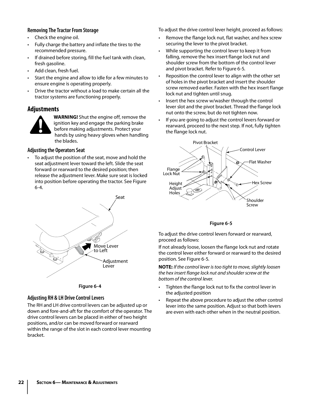
To adjust the drive control lever height, proceed as follows:
•Remove the flange lock nut, flat washer, and hex screw securing the lever to the pivot bracket.
•While supporting the control lever to keep it from falling, remove the hex insert flange lock nut and shoulder screw from the bottom of the control lever and pivot bracket. Refer to Figure
•Reposition the control lever to align with the other set of holes in the pivot bracket and insert the shoulder screw removed earlier. Fasten with the hex insert flange lock nut and tighten until snug.
•Insert the hex screw w/washer through the control lever slot and the pivot bracket. Thread the flange lock nut onto the screw, but do not tighten now.
•If you are going to adjust the control levers forward or rearward, proceed to the next step. If not, fully tighten the flange lock nut.
| Pivot Bracket |
| Control Lever |
| Flat Washer |
Flange |
|
Lock Nut |
|
Height | Hex Screw |
Adjust |
|
Holes |
|
| Shoulder |
| Screw |
Figure
To adjust the drive control levers forward or rearward, proceed as follows:
If not already loose, loosen the flange lock nut and rotate the control lever either forward or rearward to the desired position. See Figure
NOTE: If the control lever is too tight to move, slightly loosen the hex insert flange lock nut and shoulder screw at the bottom of the control lever.
•Tighten the flange lock nut to fix the control lever in the adjusted position
•Repeat the above procedure to adjust the other control lever into the same position. Adjust so that both levers are even with each other when in the neutral position.
22
Section 6— Maintenance & Adjustments