Section
2Assembly
WARNING
To prevent personal injury or property damage, do not start the engine until all assembly steps are complete and you have read and understand the safety and operating instructions in this manual.
Introduction
Carefully follow these assembly steps to correctly prepare your tiller for use. It is recommended that you read this Section in its entirety before beginning assembly.
NOTE: Three different Horse model tillers are covered in this Manual. Use only the information applicable to your model.
Tiller engines vary by model. Your engine may appear differently than those found in illustrations of this manual.
Inspect Unit
Inspect the unit and carton for damage immediately after delivery. Contact the carrier (trucking company) if you find or suspect damage. Inform them of the damage and request instructions for filing a claim. To protect your rights, put your claim in writing and mail a copy to the carrier within 15 days after the unit has been delivered. Contact us at the Factory if you need assistance in this matter.
STEP 1: Unpacking Instructions
NOTE: Do not severely bend any of the control cables on the unit.
1. The tiller is heavy. Do not attempt to remove it from the shipping platform until instructed to do so in these Assembly steps.
2.Remove all unassembled parts from the carton. The hardware bag is included in your literature packaging.
3.Check that you have the items listed below (contact your local dealer or the
Factory if any items are missing or damaged).
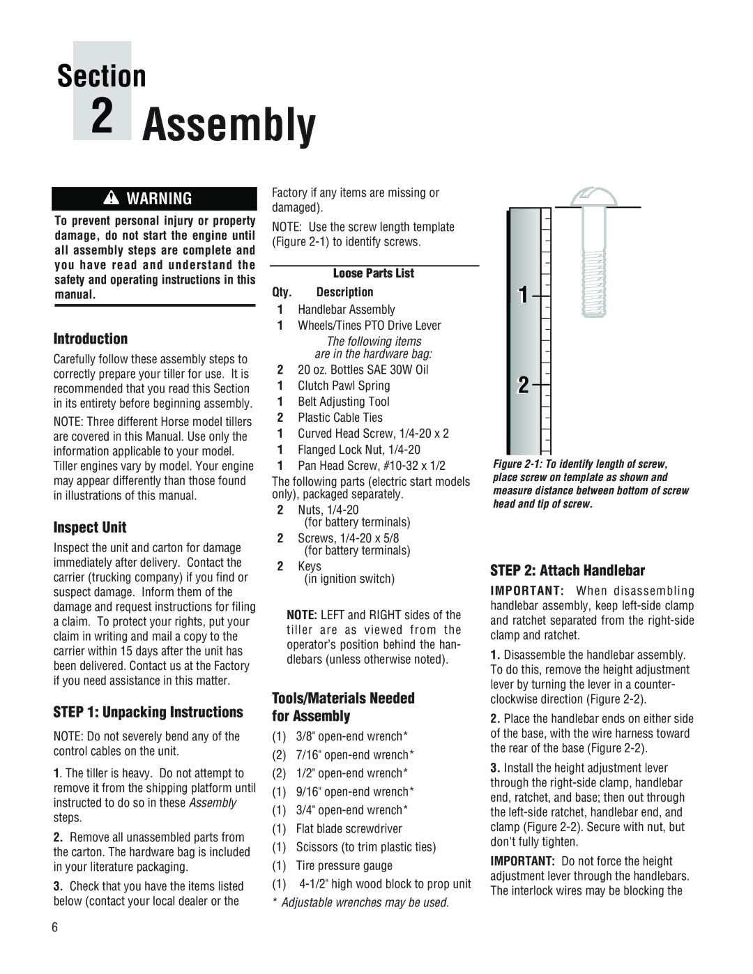
NOTE: Use the screw length template (Figure
Loose Parts List
Qty. Description
1Handlebar Assembly
1Wheels/Tines PTO Drive Lever
The following items are in the hardware bag:
220 oz. Bottles SAE 30W Oil
1Clutch Pawl Spring
1Belt Adjusting Tool
2Plastic Cable Ties
1Curved Head Screw,
1Flanged Lock Nut,
1Pan Head Screw,
The following parts (electric start models only), packaged separately.
2Nuts,
(for battery terminals)
2Screws,
2Keys
(in ignition switch)
NOTE: LEFT and RIGHT sides of the tiller are as viewed from the operator’s position behind the han- dlebars (unless otherwise noted).
Tools/Materials Needed for Assembly
(1)3/8"
(2)7/16"
(2) 1/2"
(1) 9/16"
(1) 3/4"
(1) Flat blade screwdriver
(1) Scissors (to trim plastic ties)
(1) Tire pressure gauge
(1)
1 |
2 |
Figure 2-1: To identify length of screw, place screw on template as shown and measure distance between bottom of screw head and tip of screw.
STEP 2: Attach Handlebar
IMPORTANT: When disassembling handlebar assembly, keep
1.Disassemble the handlebar assembly. To do this, remove the height adjustment lever by turning the lever in a counter- clockwise direction (Figure
2.Place the handlebar ends on either side of the base, with the wire harness toward the rear of the base (Figure
3.Install the height adjustment lever through the
IMPORTANT: Do not force the height adjustment lever through the handlebars. The interlock wires may be blocking the
6