Section 5: Maintenance
WARNING
Before inspecting, cleaning or servicing the machine, shut off engine, wait for all moving parts to come to a complete stop, disconnect spark plug wire and move wire away from spark plug. Remove ignition key, if so equipped.
Failure to follow these instructions can result in serious personal injury or property damage.
Figure 5-19: Move top half of belt over pulley and reverse disc.
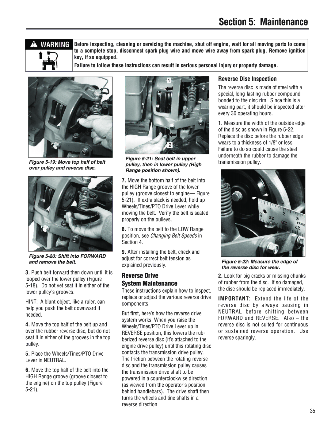
Figure 5-20: Shift into FORWARD and remove the belt.
3.Push belt forward then down until it is looped over the lower pulley (Figure
HINT: A blunt object, like a ruler, can help you push the belt downward if needed.
4.Move the top half of the belt up and over the rubber reverse disc, but do not seat it in either of the grooves in the top pulley.
5.Place the Wheels/Tines/PTO Drive Lever in NEUTRAL.
6.Move the top half of the belt into the HIGH Range groove (groove closest to the engine) on the top pulley (Figure
➦
➦
Figure 5-21: Seat belt in upper pulley, then in lower pulley (High Range position shown).
7.Move the bottom half of the belt into the HIGH Range groove of the lower pulley (groove closest to engine— Figure
8.To move the belt to the LOW Range position, see Changing Belt Speeds in Section 4.
9.After installing the belt, check and adjust for correct belt tension as explained previously.
Reverse Drive
System Maintenance
These instructions explain how to inspect, replace or adjust the various reverse drive components.
But first, here’s how the reverse drive system works: When you raise the Wheels/Tines/PTO Drive Lever up in REVERSE position, this lowers the rub- berized reverse disc (it’s attached to the engine drive pulley) until this rotating disc contacts the transmission drive pulley. The friction between the rotating reverse disc and the transmission pulley causes the transmission drive shaft to be powered in a counterclockwise direction (as viewed from the operator’s position behind handlebars). The drive shaft then turns the wheels and tine shafts in a reverse direction.
Reverse Disc Inspection
The reverse disc is made of steel with a special,
1.Measure the width of the outside edge of the disc as shown in Figure
Figure 5-22: Measure the edge of the reverse disc for wear.
2.Look for big cracks or missing chunks of rubber from the disc. If so damaged, the disc should be replaced immediately.
IMPORTANT: Extend the life of the reverse disc by always pausing in NEUTRAL before shifting between FORWARD and REVERSE. Also – the reverse disc is not suited for continuous or sustained reverse operation. Use reverse sparingly.
35