Section 2: Assembly
lever and could be damaged. You may gently move the wires aside if this condition occurs.
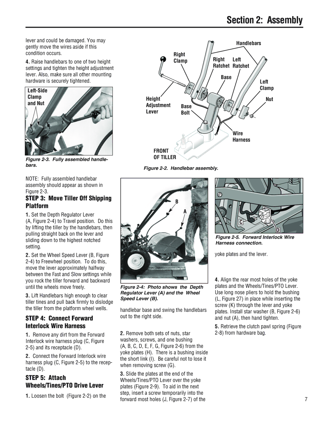
4.Raise handlebars to one of two height settings and tighten the height adjustment lever. Also, make sure all other mounting hardware is securely tightened.
Clamp
and Nut
Figure 2-3. Fully assembled handle- bars.
Handlebars
Right
ClampRight Left
Ratchet Ratchet
| Base |
| Left |
| Clamp |
Height | Nut |
Adjustment | Base |
Lever | Bolt |
| Wire |
| Harness |
FRONT
OF TILLER
Figure 2-2. Handlebar assembly.
NOTE: Fully assembled handlebar assembly should appear as shown in Figure
STEP 3: Move Tiller Off Shipping Platform
1.Set the Depth Regulator Lever
(A, Figure 2-4) to Travel position. Do this by lifting the tiller by the handlebars, then pulling straight back on the lever and sliding down to the highest notched setting.
2.Set the Wheel Speed Lever (B, Figure
3.Lift Handlebars high enough to clear
tiller tines and pull back firmly to dislodge the tiller from the platform wheel wells.
STEP 4: Connect Forward Interlock Wire Harness
1.Remove any dirt from the Forward Interlock wire harness plug (C, Figure
2.Connect the Forward Interlock wire harness plug (C, Figure
STEP 5: Attach Wheels/Tines/PTO Drive Lever
1. Loosen the bolt (Figure
B
A
Figure 2-4: Photo shows the Depth Regulator Lever (A) and the Wheel Speed Lever (B).
handlebar base and swing the handlebars out to the right side.
2.Remove both sets of nuts, star washers, screws, and one bushing
(A, B, C, D, E, F, G, Figure
3.Slide the plates at the end of the Wheels/Tines/PTO Lever over the yoke plates (Figure
C |
D |
Figure 2-5. Forward Interlock Wire Harness connection.
yoke plates and the lever.
4.Align the rear most holes of the yoke plates and the Wheels/Tines/PTO Lever. Use long nose pliers to hold the bushing (L, Figure 27) in place while inserting the screw (K) through the lever and yoke plates. Install star washer (B, Figure
5.Retrieve the clutch pawl spring (Figure
7