Wireless Access Point Model | User Manual | Page 8 of 33 |
Access Point Ports
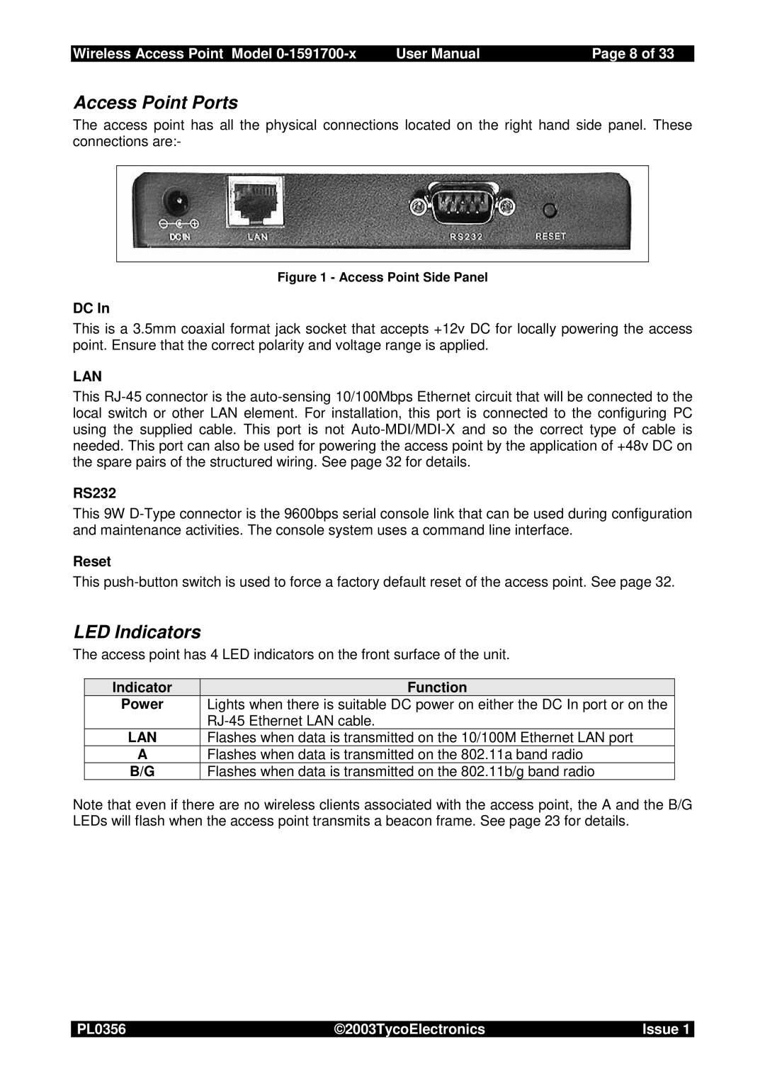
The access point has all the physical connections located on the right hand side panel. These connections are:-
Figure 1 - Access Point Side Panel
DC In
This is a 3.5mm coaxial format jack socket that accepts +12v DC for locally powering the access point. Ensure that the correct polarity and voltage range is applied.
LAN
This
RS232
This 9W
Reset
This
LED Indicators
The access point has 4 LED indicators on the front surface of the unit.
Indicator | Function |
Power | Lights when there is suitable DC power on either the DC In port or on the |
| |
LAN | Flashes when data is transmitted on the 10/100M Ethernet LAN port |
AFlashes when data is transmitted on the 802.11a band radio
B/G | Flashes when data is transmitted on the 802.11b/g band radio |
Note that even if there are no wireless clients associated with the access point, the A and the B/G LEDs will flash when the access point transmits a beacon frame. See page 23 for details.
PL0356 | ©2003TycoElectronics | Issue 1 |