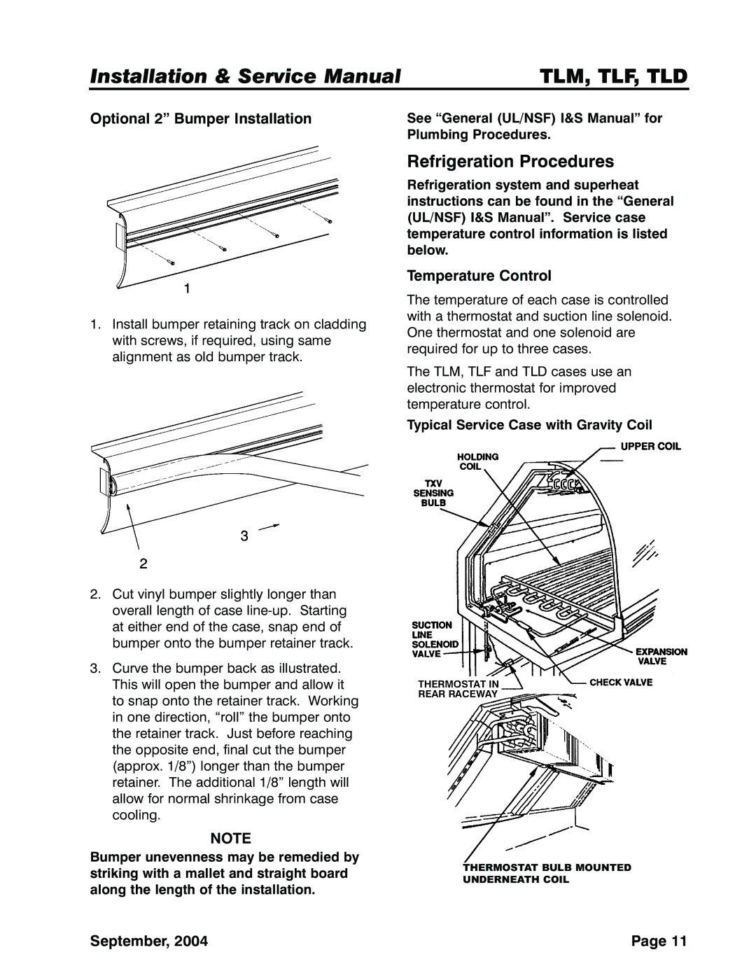
TLM, TLD, TLF specifications
Tyler Refrigeration is a recognized leader in the refrigeration industry, providing innovative solutions aimed at enhancing energy efficiency and performance. Among their suite of products, the TLF, TLD, and TLM series stand out for their cutting-edge features and technologies.The TLF series is particularly designed for accommodating large quantities of perishable goods. One of its key characteristics is the use of advanced insulation materials that not only enhance thermal efficiency but also reduce energy consumption. The TLF units come equipped with a user-friendly digital display that allows easy monitoring and precise temperature control. Additionally, the refrigeration system uses environmentally friendly refrigerants, ensuring compliance with modern sustainability standards.
The TLD series is optimized for versatility in commercial applications. These units are characterized by their adjustable shelving, which allows for flexible storage configurations. Moreover, the TLD series features a robust build quality, ensuring durability in high-traffic environments. An integrated energy management system is a highlight of the TLD line, providing real-time energy consumption data and helping operators to better understand their usage patterns. This feature not only aids in cost-saving measures but also aligns with broader efforts for environmental sustainability.
The TLM series focuses on maximizing space efficiency without sacrificing performance. What separates TLM from other models is its compact design, which is ideal for establishments with limited space such as convenience stores and small restaurants. The units utilize a state-of-the-art cooling technology, which guarantees even temperature distribution throughout the interior. The TLM series also incorporates smart technology, enabling remote monitoring and diagnostics. This capability allows operators to receive alerts for any temperature fluctuations or mechanical issues, ensuring the safety of stored products.
All three series feature a sleek design, allowing them to blend seamlessly into various environments, from grocery stores to industrial kitchens. Tyler Refrigeration has prioritized user convenience, ensuring that regular maintenance tasks can be performed easily, thus decreasing downtime.
In conclusion, Tyler Refrigeration's TLF, TLD, and TLM series showcase the company's commitment to innovation, efficiency, and reliability. With their unique features and modern technologies, these units not only enhance operational capabilities but also support sustainability in the refrigeration landscape. Whether for large-scale storage or compact applications, Tyler Refrigeration continues to set the standard for excellence in refrigeration solutions.

