3 Prepare Site
Your
Note: Unit can NOT be installed behind a closed cabinet door.
Cut-Out Dimensions
| Filler Panel (Not Provided by |
| May Be Added Above or Below Unit |
| to Enclose for a |
Typical |
|
Counter |
|
Height | |
See Electrical | |
to | |
Specifications | |
for Power Supply | |
| |
Height |
|
| |
to |
|
25" | 8" |
| |
| |
Figure 1 |
|
Follow the
IMPORTANT
It is extremely important that the unit sits on a level surface, as it does not have feet levelers. If it is not level, the ice mold will not fill evenly.
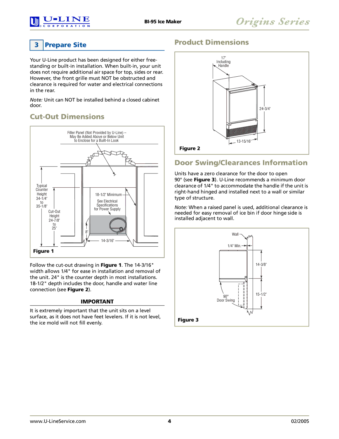
Product Dimensions
17"
Including
Handle
Figure 2
Door Swing/Clearances Information
Units have a zero clearance for the door to open
90° (see Figure 3).
Note: When a raised panel is used, additional clearance is needed for easy removal of ice bin if door hinge side is installed adjacent to wall.
Wall
1/4" Min.
90° | ||
Door Swing |
|
|
|
|
|
|
|
|
Figure 3
4 | 02/2005 |