Manuals
/
Unified Brands
/
Kitchen Appliance
/
Ventilation Hood
Unified Brands
VENTILATION SYSTEMS
specifications
a b
Models:
VENTILATION SYSTEMS
1
9
33
33
Download
33 pages
54.59 Kb
6
7
8
9
10
11
12
13
Parts list
Error! Not a valid link
b. Setting the PAWS
Cleaner/Degreaser
Page 9
Image 9
Page 8
Page 10
Page 9
Image 9
Page 8
Page 10
Contents
OPERATORS MANUAL
VENTILATION SYSTEMS
1055 Mendell Davis Drive Jackson, MS
888-994-7636,fax avtecind.com
TABLE OF CONTENTS
Air Adjustment Baffle
VENTILATOR FEATURES AND ACCESSORIES
PERIODIC MAINTENANCE
G. Fusible Link Replacement
1I. TYPES OF SYSTEMS
Installation shall be in accordance with NFPA
NOTE Welds must not impede operation of damper
Page
Page
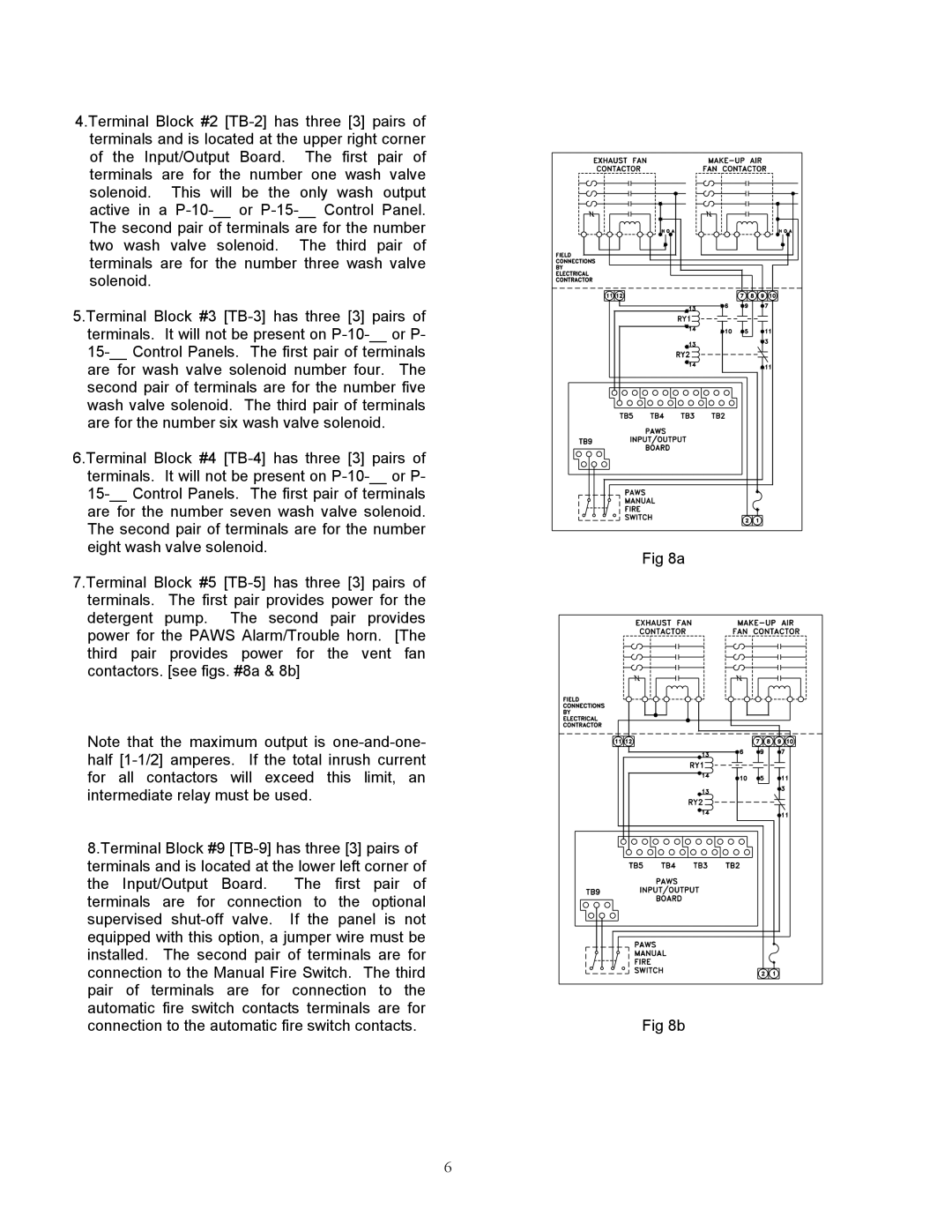
Fig 8a Fig 8b
9.Terminal Block #11 TB-11has three 3 pairs of terminals. The first pair of terminals are low voltage connections for the detergent low level probe. The probe should be installed in the detergent container so that it does not protrude above the top of the detergent pump inlet strainer. fig. #9 This is intended to prevent cavitation of the pump and will advise when the tank needs to be refilled. The probe rods may be cut to facilitate a neat and effective installation
For authorized sevice techinician use only
Terminal Block Designation
Error! Not a valid link
Page
VI. OPERATION
vac as long as the START Button is depressed
a. Fan Start
b. Setting the PAWS
d. Reviewing The Daily Event Schedule
OFF/WASH
Page
l. Detergent Pump and Tank
Refer to fig
E. Fire Dampers 1. Fusible Link Type
fig. 3. Slot-TypeInternal Air Make-Up
D. Grease Collection Receptacle
B. VCW PANEL - ELECTRICAL
A. PAWS PANEL - ELECTRICAL
C. PAWS/VCW PANEL - PLUMBING
ITEM NO
E. ELECTRO - MECHANICAL DAMPER
D. EVAC DETERGENT
ITEM NO
DESCRIPTION
G. HOOD CANOPY
F. FUSIBLE LINK DAMPER
ITEM NO
AVTEC PART NO
Cleaner/Degreaser
Cleaner/Degreaser
For Exhaust Ventilator Auto-washCleaner
UNIQUE, POWERFUL CLEANING FORMULA
Project Name
AIR MOVEMENT RECORDINGS
A. ENERGY AIRE HOODS - EXHAUST
B. FILTER HOODS - EXHAUST
Page
CALCULATING AND RECORDING AIR MOVEMENT
EXHAUST
SUPPLY
FOR THE NAME AND LOCATION OF THE NEAREST
AVTEC SERVICE AGENCY, CALL OR WRITE TO
Top
Page
Image
Contents