Don’t use the sprayer without having consulted the enclosed handbook
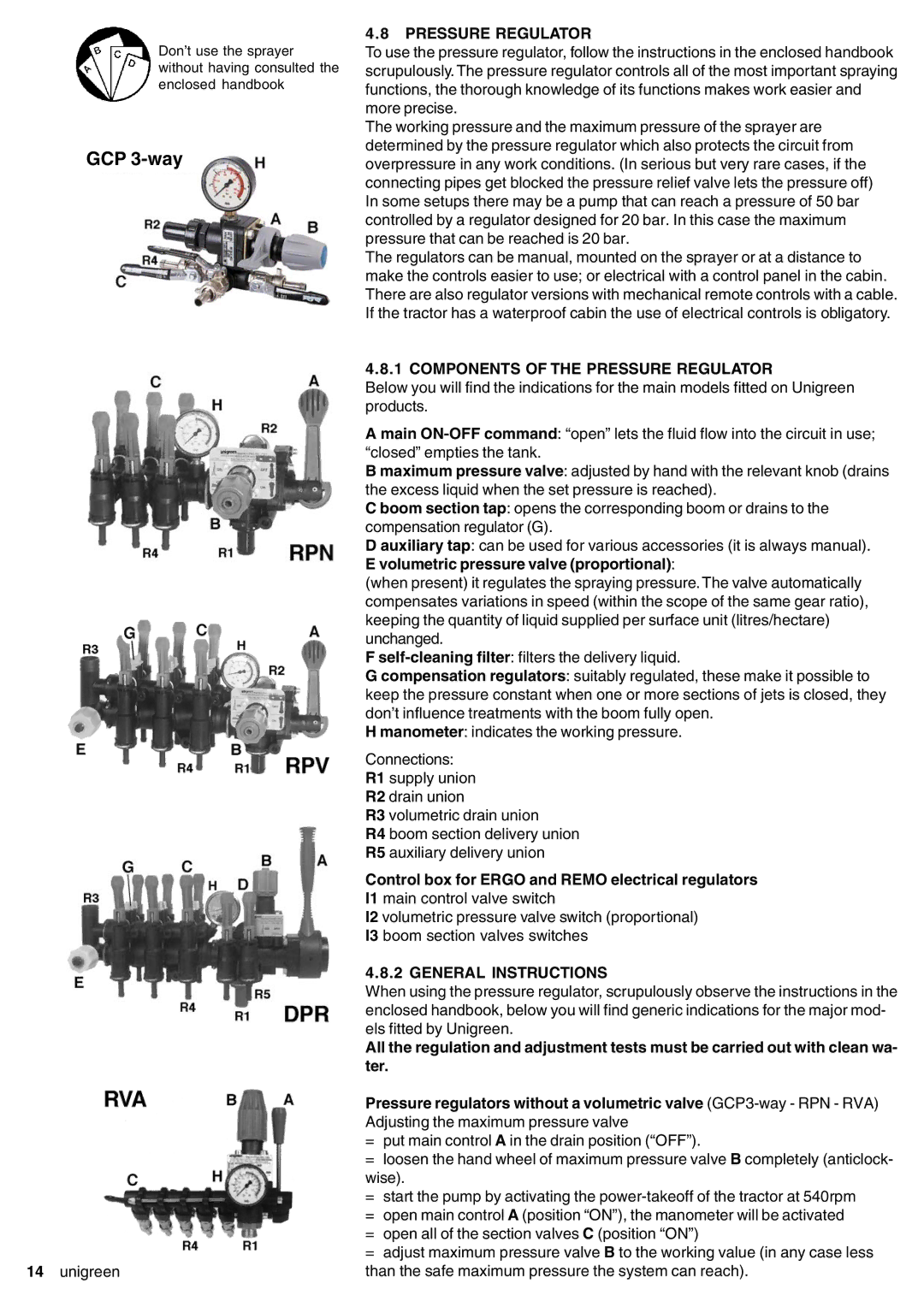
GCP 3-way
14unigreen
4.8PRESSURE REGULATOR
To use the pressure regulator, follow the instructions in the enclosed handbook scrupulously. The pressure regulator controls all of the most important spraying functions, the thorough knowledge of its functions makes work easier and more precise.
The working pressure and the maximum pressure of the sprayer are determined by the pressure regulator which also protects the circuit from overpressure in any work conditions. (In serious but very rare cases, if the connecting pipes get blocked the pressure relief valve lets the pressure off) In some setups there may be a pump that can reach a pressure of 50 bar controlled by a regulator designed for 20 bar. In this case the maximum pressure that can be reached is 20 bar.
The regulators can be manual, mounted on the sprayer or at a distance to make the controls easier to use; or electrical with a control panel in the cabin. There are also regulator versions with mechanical remote controls with a cable. If the tractor has a waterproof cabin the use of electrical controls is obligatory.
4.8.1 COMPONENTS OF THE PRESSURE REGULATOR
Below you will find the indications for the main models fitted on Unigreen products.
A main
B maximum pressure valve: adjusted by hand with the relevant knob (drains the excess liquid when the set pressure is reached).
C boom section tap: opens the corresponding boom or drains to the compensation regulator (G).
D auxiliary tap: can be used for various accessories (it is always manual). E volumetric pressure valve (proportional):
(when present) it regulates the spraying pressure. The valve automatically compensates variations in speed (within the scope of the same gear ratio), keeping the quantity of liquid supplied per surface unit (litres/hectare) unchanged.
F
G compensation regulators: suitably regulated, these make it possible to keep the pressure constant when one or more sections of jets is closed, they don’t influence treatments with the boom fully open.
H manometer: indicates the working pressure.
Connections:
R1 supply union
R2 drain union
R3 volumetric drain union
R4 boom section delivery union
R5 auxiliary delivery union
Control box for ERGO and REMO electrical regulators
I1 main control valve switch
I2 volumetric pressure valve switch (proportional)
I3 boom section valves switches
4.8.2 GENERAL INSTRUCTIONS
When using the pressure regulator, scrupulously observe the instructions in the enclosed handbook, below you will find generic indications for the major mod- els fitted by Unigreen.
All the regulation and adjustment tests must be carried out with clean wa- ter.
Pressure regulators without a volumetric valve
=put main control A in the drain position (“OFF”).
=loosen the hand wheel of maximum pressure valve B completely (anticlock- wise).
=start the pump by activating the
=open main control A (position “ON”), the manometer will be activated
=open all of the section valves C (position “ON”)
=adjust maximum pressure valve B to the working value (in any case less than the safe maximum pressure the system can reach).