2931 specifications
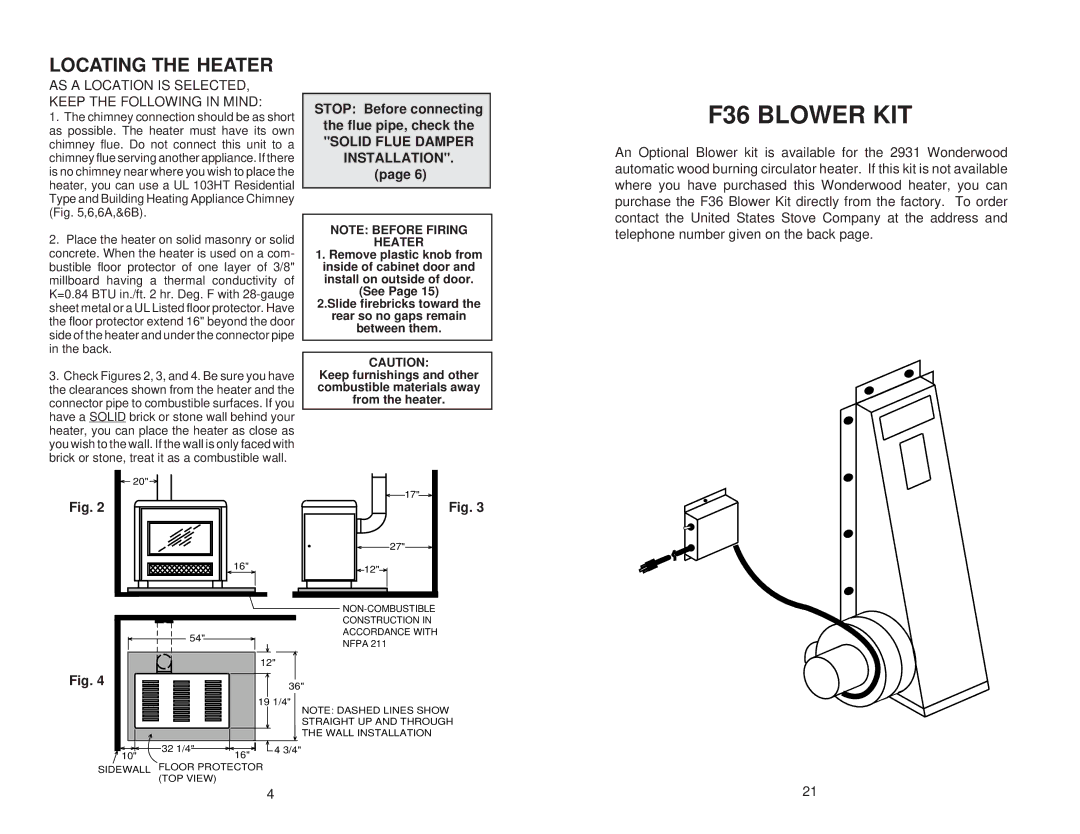
The United States Stove 2931 is a remarkable wood-burning stove that combines efficiency, style, and functionality, making it an excellent choice for homeowners seeking an effective heating solution. Designed with both aesthetics and performance in mind, this stove has garnered a reputation for its reliability and ease of use.One of the key features of the U.S. Stove 2931 is its efficient heating capacity. With a maximum heating capacity of up to 2,000 square feet, it is perfect for medium to large-sized spaces. The stove is designed to provide long burn times, ensuring that your home stays warm and cozy even during the coldest winter nights. Users can expect an impressive burn time that can stretch up to 8 hours, depending on the type of wood used and the load size.
The stove is constructed from heavy-duty cast iron and steel, providing durability and extended service life. Its robust build ensures that it can withstand high temperatures, while also allowing for better heat retention. The combination of materials also enhances the overall aesthetic appeal of the stove, making it a stylish addition to any room.
One of the standout technologies integrated into the U.S. Stove 2931 is the unique air control system. This system allows users to easily regulate the airflow into the stove, enhancing combustion efficiency. By controlling the air intake, homeowners can optimize the burn rate, extending fuel efficiency and significantly reducing smoke emissions. This not only contributes to a cleaner environment but also ensures that the stove meets stringent EPA guidelines.
Additionally, the U.S. Stove 2931 features a large viewing window, allowing users to enjoy the visual ambiance of the flames while also monitoring the fire's behavior. This glass window is designed to withstand high temperatures and is positioned for optimal visibility, adding a welcoming touch to the living space.
The stove is equipped with an easily accessible ash pan, simplifying the cleaning process. This feature ensures that maintenance is hassle-free, allowing users to spend more time enjoying the comforting warmth of their stove and less time on upkeep.
In conclusion, the United States Stove 2931 is a well-crafted, efficient wood-burning stove that offers a combination of functionality, durability, and style. With its impressive heating capacity, effective air control system, and user-friendly design, this stove is an ideal choice for anyone looking to enhance their home heating experience.

