GUIDELINES FOR EXHAUST VENTING SYSTEMS DESIGN
It is recommended that only an authorized installer install your
INSTALL VENT AT CLEARANCES SPECIFIED BY THE VENT MANUFACTURER.
•A UL listed 3” or 4” type “PL” pellet vent exhaust system must be used for installation and attached to the pipe connector provided on the back of the heater. Use a 3” to 4” adapter for 4” pipe. A cap must be used at the termination of type “L” vent chimneys. 4” PL is required for elevations above 2,500 feet above sea level.
•Do not terminate vent in any enclosed or
•Vent surfaces can get hot enough to cause burns if touched by children. Noncombustible shielding or guards may be required.
•Do not install a flue damper in the exhaust vent of this unit.
•Termination must exhaust above air inlet elevation. Installation MUST include three (3) vertical feet of pellet vent pipe. This will create some natural draft to prevent the possibility of smoke or odor during appliance shutdown and to keep exhaust from caus- ing a nuisance or hazard from exposing people or shrubs to high temperatures. Do not connect this unit to a chimney flue serving another appliance. Do not connect directly to a masonry chimney.
•The installation must include a cleanout tee to enable collection of fly ash and to permit periodic cleaning of the exhaust system. 90° elbows accumulate fly ash and soot thereby reducing exhaust flow and performance of the heater. Each elbow or tee reduces draft potential by 30% to 50%. Use no more than 180 degrees of elbows (two
•Total length of horizontal vent must not exceed 48”(4ft.)/1,200mm. The maximum recommended vertical venting height is
•The area where the vent pipe penetrates to the exterior of the home must be sealed with silicone or other means to maintain the vapor barrier between the exterior and the interior of the home.
NOTE: These are guidelines only. Proper venting is accomplished by design and necessary requirements. In most installations 3 inch diameter venting is adequate. If it does not vent properly you will have to change it to 4 inches. You should not exceed 4 inch diameter venting.
DO NOT CONNECT TO ANY AIR DISTRIBUTION DUCT OR SYSTEM
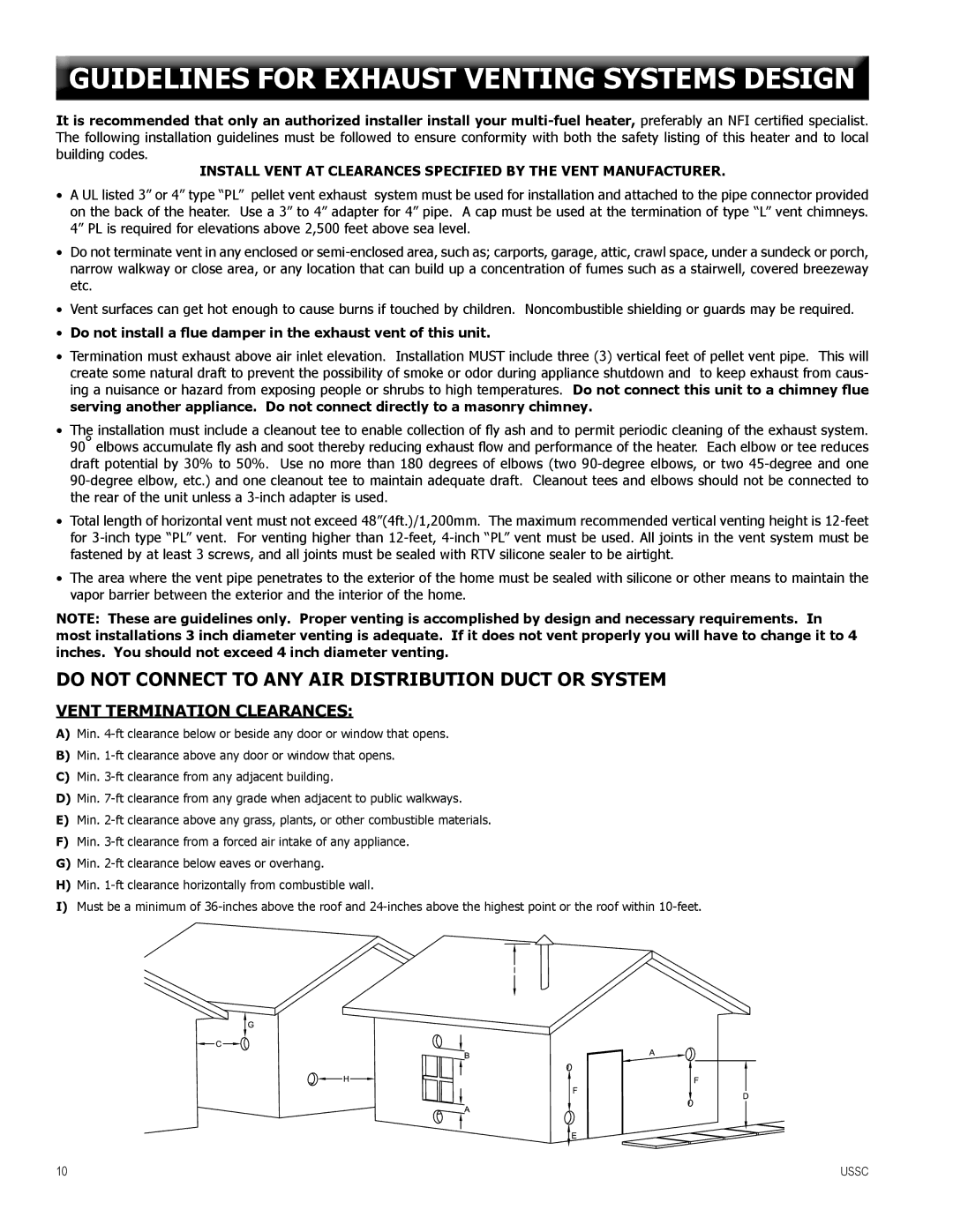
VENT TERMINATION CLEARANCES:
A)Min.
B)Min.
C)Min.
D)Min.
E)Min.
F)Min.
G)Min.
H)Min.
I)Must be a minimum of
10 | USSC |