Universal Remote Control MRF-300/RFX150 Daisy Chain Multiple MRF-300’s to One RFX-150 RF Sensor

Models: MRF-300/RFX150

1 16
Download 16 pages 28.59 Kb
Page 7
Image 7

MRF-300 BASE STATION

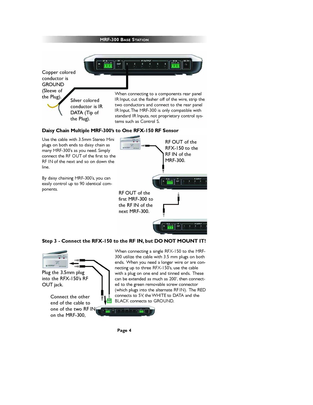
Copper colored conductor is

GROUND (Sleeve of the Plug).

Silver colored conductor is IR DATA (Tip of the Plug).

When connecting to a components rear panel IR Input, cut the flasher off of the wire, strip the two conductors and connect to the rear panel IR Input.The MRF-300 is only compatible with standard IR Inputs, not proprietary control sys- tems such as Control S.

Daisy Chain Multiple MRF-300’s to One RFX-150 RF Sensor

Use the cable with 3.5mm Stereo Mini plugs on both ends to daisy chain as many MRF-300’s as you need. Simply connect the RF OUT of the first to the RF IN of the next and so on down the line.

By daisy chaining MRF-300’s, you can easily control up to 90 identical com- ponents.

RF OUT of the first MRF-300 to the RF IN of the next MRF-300.

RF OUT of the RFX-150 to the RF IN of the MRF-300.

Step 3 - Connect the RFX-150 to the RF IN, but DO NOT MOUNT IT!

Plug the 3.5mm plug into the RFX-150’s RF OUT jack.

Connect the other end of the cable to one of the two RF IN on the MRF-300,

When connecting a single RFX-150 to the MRF- 300 utilize the cable with 3.5 mm plugs on both ends. When you need a longer wire or are con- necting up to three RFX-150’s, use the cable with a plug on one end and tinned ends. These can be extended as much as 200’, then connect- ed to the green removable screw connector (which plugs into the alternate RF IN). The RED connects to 5V, the WHITE to DATA and the BLACK connects to GROUND.

Page 4

Page 7
Image 7
Universal Remote Control MRF-300/RFX150 installation manual Daisy Chain Multiple MRF-300’s to One RFX-150 RF Sensor