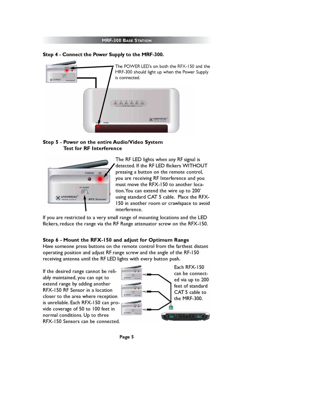
Step 4 - Connect the Power Supply to the MRF-300.
![]() The POWER LED’s on both the
The POWER LED’s on both the
Step 5 - Power on the entire Audio/Video System
Test for RF Interference
The RF LED lights when any RF signal is detected. If the RF LED flickers WITHOUT pressing a button on the remote control, you are receiving RF Interference and you must move the
If you are restricted to a very small range of mounting locations and the LED flickers, reduce the range via the RF Range attenuator screw on the
Step 6 - Mount the RFX-150 and adjust for Optimum Range
Have someone press buttons on the remote control from the farthest distant operating position and adjust RF range screw and the angle of the
If the desired range cannot be reli- ably maintained, you can opt to extend range by adding another
Each
Page 5