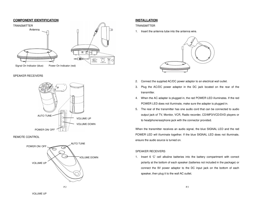
SPK-VELO-001 specifications
Velocity Micro has made a significant mark in the realm of personal computing with its SPK-VELO-001, a sleek and versatile product designed for both casual users and tech enthusiasts. This compact system brings together powerful performance, innovative technology, and user-friendly features, making it an appealing choice for a wide range of applications.One of the standout features of the SPK-VELO-001 is its advanced processing power. Equipped with the latest generation Intel Core processors, it ensures that users experience smooth multitasking and responsive performance for demanding applications, whether for gaming, content creation, or standard office tasks. This processing capability is complemented by high-speed DDR4 RAM, allowing for quick data access and efficient handling of multiple applications simultaneously.
Storage is another critical aspect of the SPK-VELO-001. With options for both solid-state drives (SSDs) and traditional hard disk drives (HDDs), users have the flexibility to choose the setup that best suits their needs. The inclusion of SSDs provides fast boot times and quick load times for applications, enhancing user experience significantly.
Connectivity is a key priority for modern devices, and the SPK-VELO-001 excels in this area too. It offers a variety of ports including USB-C, USB 3.0, HDMI, and Ethernet, ensuring users can connect to a multitude of peripherals and high-resolution displays. Additionally, it supports Wi-Fi 6 technology, which delivers faster wireless connectivity and improved network performance, making it ideal for streaming and online gaming.
In terms of design, the SPK-VELO-001 stands out with its sleek, modern aesthetics. Its compact size makes it easy to integrate into any workspace, whether at home or in a professional environment. The thoughtful arrangement of internal components also aids in cooling, ensuring that performance remains high even under heavy loads.
The SPK-VELO-001 is built with upgradability in mind. Users have the option to expand their memory and storage options, allowing for future-proofing and adaptability as their computational needs evolve.
Overall, the Velocity Micro SPK-VELO-001 encapsulates everything that modern computing demands, with a combination of power, flexibility, and user-centric design. Whether for work or play, it is a system that promises to deliver exceptional performance and reliability.

