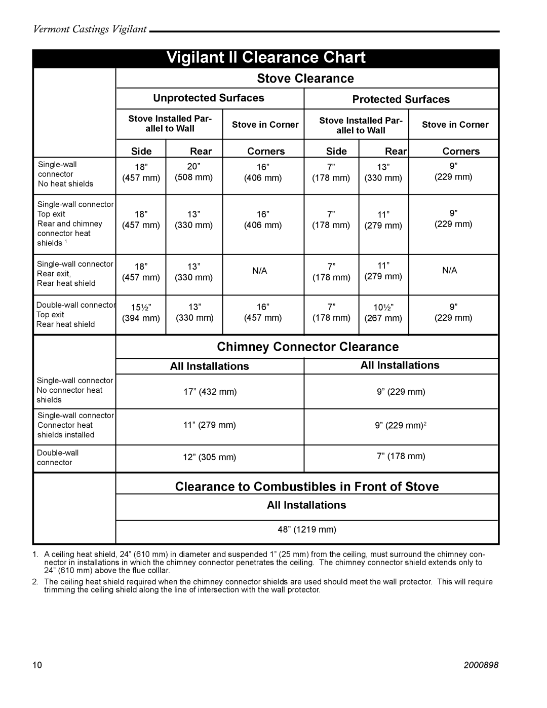
2310 specifications
Vermont Casting 2310 is a celebrated addition to the family of cast-iron wood stoves, combining vintage charm with modern functionality. It boasts both aesthetic appeal and superior heating capabilities, making it a popular choice for homeowners seeking an efficient and reliable heating solution.One of the main features of the Vermont Casting 2310 is its robust construction, utilizing high-quality cast iron renowned for excellent heat retention and distribution. This material not only ensures durability but also adds to the stove's timeless appearance. The 2310 model is elegantly designed with clean lines and a classic finish, available in various colors to complement any home decor.
The Vermont Casting 2310 is equipped with advanced technology that enhances its performance. One such feature is its efficient combustion system, which promotes a cleaner burn by maximizing fuel utilization. This results in fewer emissions and less creosote buildup, making it an environmentally friendly option. The air wash system keeps the glass door clean, ensuring you always have a clear view of the beautiful flames, enhancing the cozy atmosphere that a wood stove brings to any space.
Another standout characteristic of the 2310 is its adaptability. It can accommodate a range of firewood sizes and types, allowing users to choose the most convenient and economical fuel sources. Additionally, the stove features a convenient ash pan that simplifies clean-up, making maintenance hassle-free.
The Vermont Casting 2310 is designed with user comfort in mind. The large firebox provides ample space for fuel, extending burn times and requiring less frequent loading. The adjustable airflow controls allow users to customize heat output, giving them complete control over their heating needs.
Safety is also a priority in the design of the 2310, with features like a built-in thermostat and a safety shut-off system. These features ensure optimal operation and peace of mind, so you can enjoy the warmth and glow of your wood stove without worry.
Overall, the Vermont Casting 2310 combines classic design with modern technology, offering efficiency, reliability, and aesthetic appeal. Whether heating a cabin in the woods or enhancing a family home's ambiance, it stands out as a top choice for wood-burning enthusiasts.

