Installation Instructions
2 INSTALLATION
1INSTALL THE MOUNTING PLATE
•Always mount the mounting plate horizontally.
•Attach the mounting plate at the selected location with screws supplied with the unit .
•Be sure that the mounting plate has been attached firmly enough to withstand the weight of an adult of 130 lbs. Also, the weight should be evenly shared by each screw.
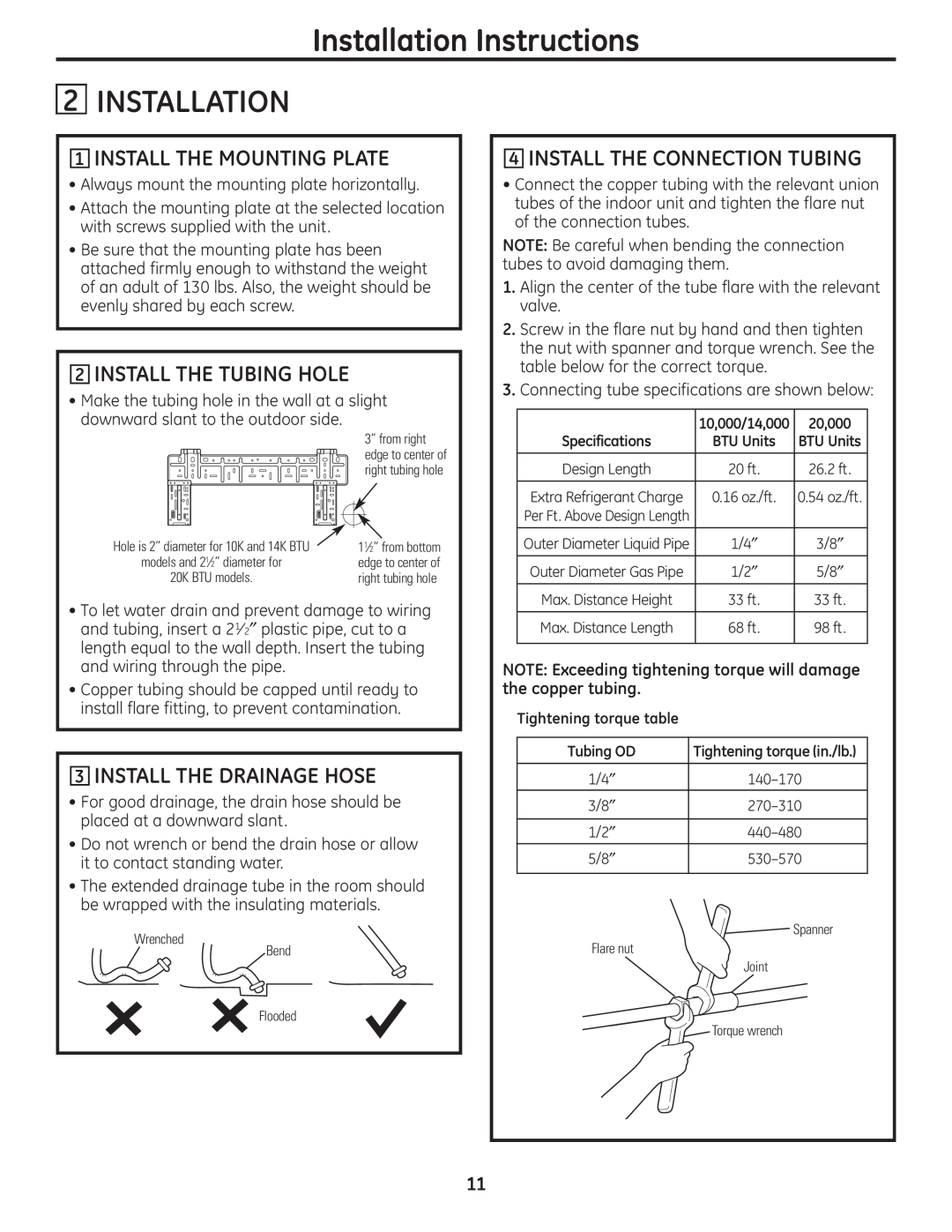
2INSTALL THE TUBING HOLE
•Make the tubing hole in the wall at a slight downward slant to the outdoor side.
3” from right edge to center of right tubing hole
Hole is 2” diameter for 10K and 14K BTU | 11⁄2” from bottom |
models and 21⁄2” diameter for | edge to center of |
20K BTU models. | right tubing hole |
|
|
•To let water drain and prevent damage to wiring and tubing, insert a 21⁄ 2″ plastic pipe, cut to a length equal to the wall depth. Insert the tubing and wiring through the pipe.
•Copper tubing should be capped until ready to install flare fitting, to prevent contamination.
3INSTALL THE DRAINAGE HOSE
•For good drainage, the drain hose should be placed at a downward slant .
•Do not wrench or bend the drain hose or allow it to contact standing water.
•The extended drainage tube in the room should be wrapped with the insulating materials.
Wrenched
Bend
Flooded
4INSTALL THE CONNECTION TUBING
•Connect the copper tubing with the relevant union tubes of the indoor unit and tighten the flare nut of the connection tubes.
NOTE: Be careful when bending the connection tubes to avoid damaging them.
1.Align the center of the tube flare with the relevant valve.
2.Screw in the flare nut by hand and then tighten the nut with spanner and torque wrench. See the table below for the correct torque.
3.Connecting tube specifications are shown below:
| 10,000/14,000 | 20,000 |
Specifications | BTU Units | BTU Units |
|
|
|
Design Length | 20 ft. | 26.2 ft. |
|
|
|
Extra Refrigerant Charge | 0.16 oz./ft. | 0.54 oz./ft. |
Per Ft. Above Design Length |
|
|
|
|
|
Outer Diameter Liquid Pipe | 1/4″ | 3/8″ |
|
|
|
Outer Diameter Gas Pipe | 1/2″ | 5/8″ |
|
|
|
Max. Distance Height | 33 ft. | 33 ft. |
|
|
|
Max. Distance Length | 68 ft. | 98 ft. |
|
|
|
NOTE: Exceeding tightening torque will damage the copper tubing.
Tightening torque table
Tubing OD | Tightening torque (in./lb.) |
1/4″ | |
3/8″ | |
1/2″ | |
5/8″ | |
| Spanner |
Flare nut |
|
| Joint |
| Torque wrench |
11