Hole sizes listed in Figure 10 for angled firestop spac- ers provide minimum required air space to chimney pipe for ceiling thickness up to 8” (203mm). When combined thickness of ceiling material, ceiling joists and flooring material exceeds 8” (203mm), adjust- ments must be made in framing to assure that mini- mum air spaces to chimney are maintained.
Proper Firestop Spacer Installation
Page 10, Figure 15 shows different installation pro- cedures for both an area that is an attic and an area that is not an attic.
If the area above the ceiling is not an attic, position the firestop spacer with the flange on the ceiling side and the angled portion extending up into the hole.
If the area above the ceiling is an attic, position the firestop spacer with the flange on the top of the framed hole and the angled portion extending down into the hole.
Firestop spacers are not available for, nor are they required on vertical walls.
DO NOT put any sealant around the area where the outer pipe slides through the firestop spacer. If you
seal this area, it may cause a fire hazard.
Canadian Requirements for
Insulation Shield
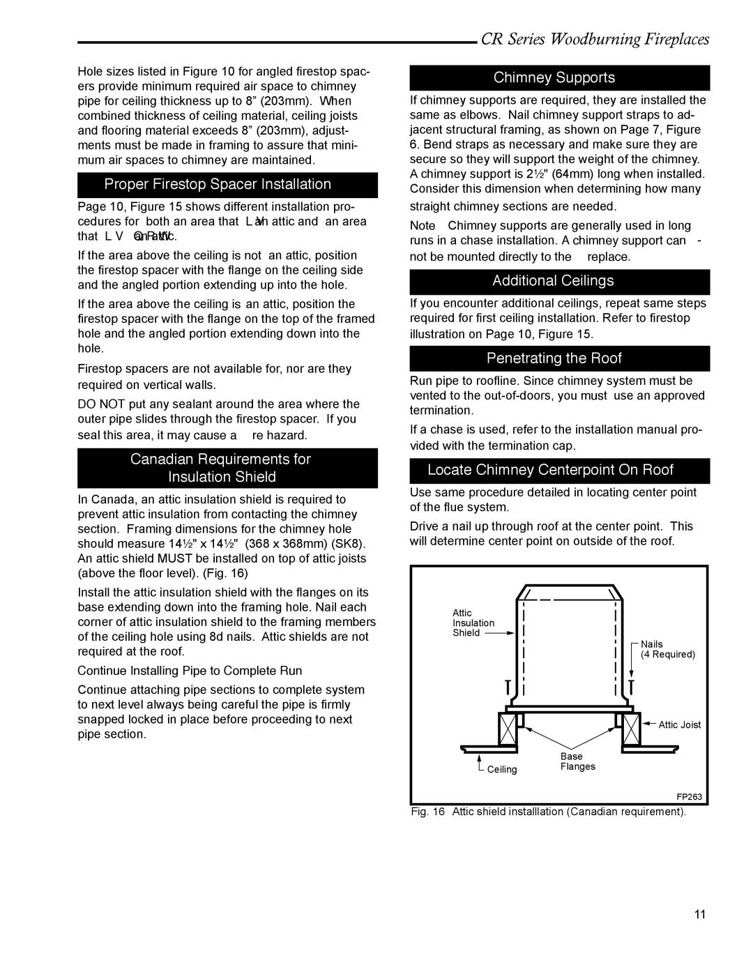
In Canada, an attic insulation shield is required to prevent attic insulation from contacting the chimney section. Framing dimensions for the chimney hole should measure 14¹⁄₂" x 14¹⁄₂" (368 x 368mm) (SK8). An attic shield MUST be installed on top of attic joists (above the floor level). (Fig. 16)
Install the attic insulation shield with the flanges on its base extending down into the framing hole. Nail each corner of attic insulation shield to the framing members of the ceiling hole using 8d nails. Attic shields are not required at the roof.
Continue Installing Pipe to Complete Run
Continue attaching pipe sections to complete system to next level always being careful the pipe is firmly snapped locked in place before proceeding to next pipe section.
CR Series Woodburning Fireplaces
Chimney Supports
If chimney supports are required, they are installed the same as elbows. Nail chimney support straps to ad- jacent structural framing, as shown on Page 7, Figure
6.Bend straps as necessary and make sure they are secure so they will support the weight of the chimney. A chimney support is 2¹⁄₂" (64mm) long when installed. Consider this dimension when determining how many straight chimney sections are needed.
Note: Chimney supports are generally used in long runs in a chase installation. A chimney support can- not be mounted directly to the fireplace.
Additional Ceilings
If you encounter additional ceilings, repeat same steps required for first ceiling installation. Refer to firestop illustration on Page 10, Figure 15.
Penetrating the Roof
Run pipe to roofline. Since chimney system must be vented to the
If a chase is used, refer to the installation manual pro- vided with the termination cap.
Locate Chimney Centerpoint On Roof
Use same procedure detailed in locating center point of the flue system.
Drive a nail up through roof at the center point. This will determine center point on outside of the roof.
Attic
Insulation
Shield ![]()
Nails
(4 Required)
![]() Attic Joist
Attic Joist
Base
![]() Ceiling Flanges
Ceiling Flanges
FP263
Fig. 16 Attic shield installlation (Canadian requirement).
20001316 | 11 |