Connection to Gas Supply
1.Place the burner pan in the fireplace. The burner pan should be located several inches form the back wall, centered from left to right. NOTE: This is for burner connection purposes only. Exact burner placement will be covered on page 8, after all connections have been made.
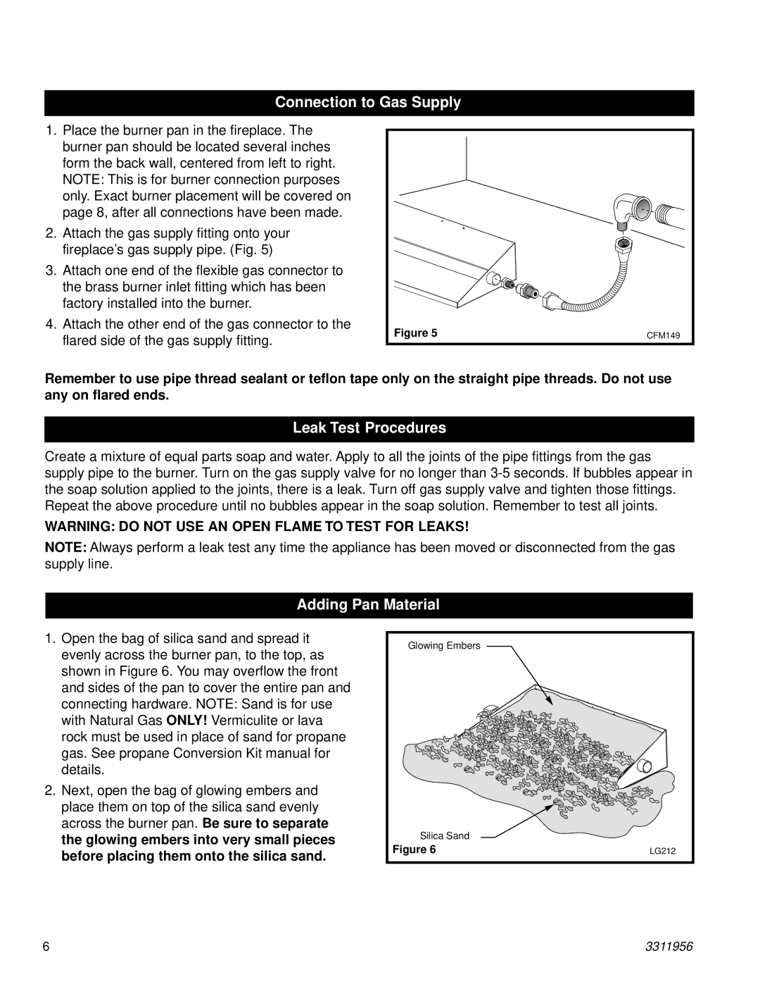
2.Attach the gas supply fitting onto your fireplace’s gas supply pipe. (Fig. 5)
3.Attach one end of the flexible gas connector to the brass burner inlet fitting which has been factory installed into the burner.
4.Attach the other end of the gas connector to the flared side of the gas supply fitting.
Figure 5 | CFM149 |
Remember to use pipe thread sealant or teflon tape only on the straight pipe threads. Do not use any on flared ends.
Leak Test Procedures
Create a mixture of equal parts soap and water. Apply to all the joints of the pipe fittings from the gas supply pipe to the burner. Turn on the gas supply valve for no longer than
WARNING: DO NOT USE AN OPEN FLAME TO TEST FOR LEAKS!
NOTE: Always perform a leak test any time the appliance has been moved or disconnected from the gas supply line.
Adding Pan Material
1.Open the bag of silica sand and spread it evenly across the burner pan, to the top, as shown in Figure 6. You may overflow the front and sides of the pan to cover the entire pan and connecting hardware. NOTE: Sand is for use with Natural Gas ONLY! Vermiculite or lava rock must be used in place of sand for propane gas. See propane Conversion Kit manual for details.
2.Next, open the bag of glowing embers and place them on top of the silica sand evenly across the burner pan. Be sure to separate the glowing embers into very small pieces before placing them onto the silica sand.
Glowing Embers |
|
Silica Sand |
|
Figure 6 | LG212 |
6 | 3311956 |