Manuals
/
Vidikron
/
Computer Equipment
/
Projector
Vidikron
100
manual
Dimensions
Models:
100
1
27
29
29
Download
29 pages
63.58 Kb
22
23
24
25
26
27
28
29
Page 27
Image 27
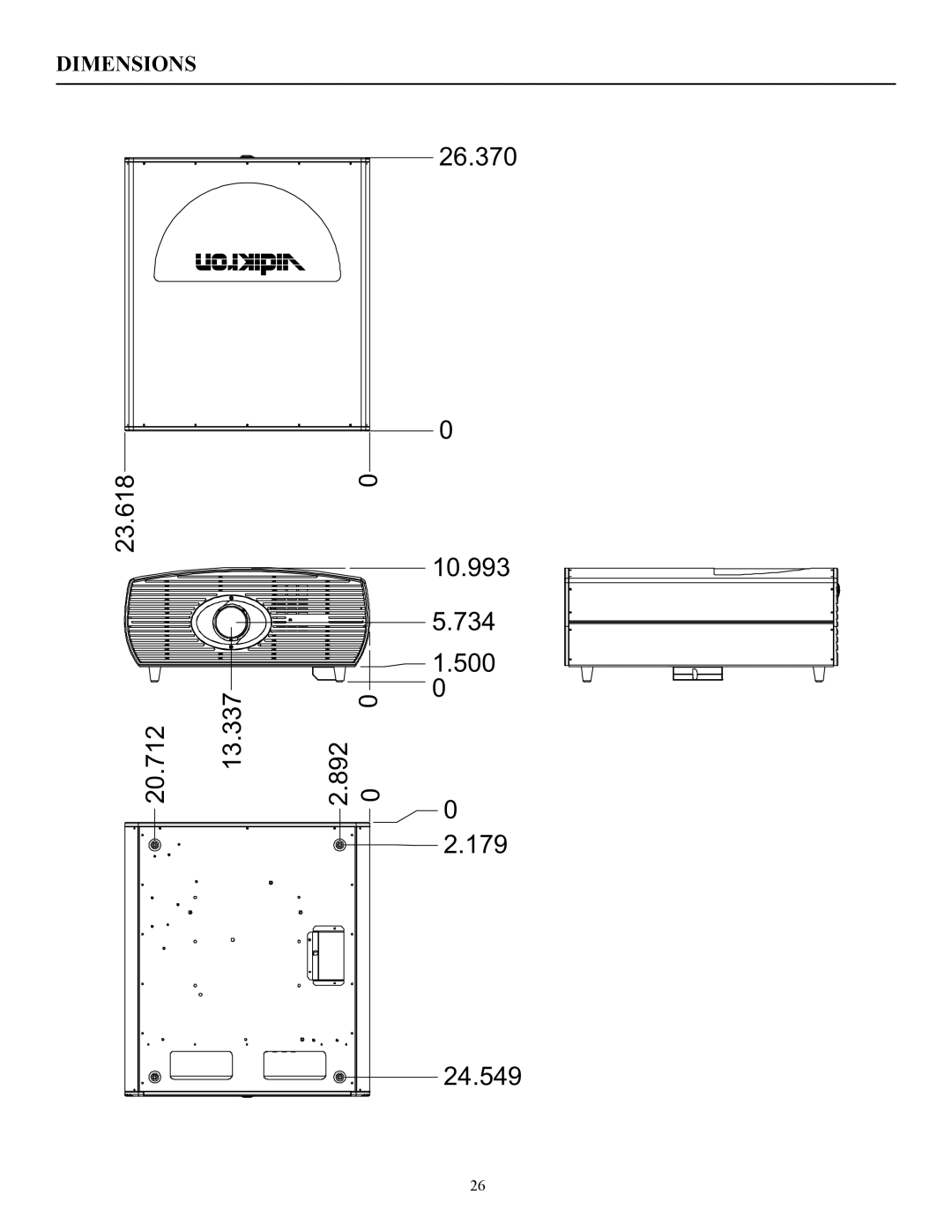
DIMENSIONS
������ �
������ ������
����� � �
������
�
������
�����
�����
�
�
�����
������
26
Page 26
Page 28
Page 27
Image 27
Page 26
Page 28
Contents
G H T a M P D L P P R O J E C T O R
Table of Contents
» Options
» The features you’ll enjoy include
» Contents of the package
Introduction
Product Disposal Information
Declaration of Conformity
Intellectual Property Rights Read Before Using the Product
Limited Warranty
TWO Year Limited Warranty
Vidikron
Effective Warranty Date
Projector Rear Panel Inputs
Video 1 Input
Video 2 Input
Vacuum Florescent Display
Main Power Switch
Power Button
RS-232 Control
ENT Enter Button
Remote Control Description
IR Output Indicator
Light Button
Comp Component Button
Memory Settings Buttons
Source Selection Buttons
Video Button
Analog Inputs
Quick Connection and Setup Guide
Connection
Step Three
HOW to Install or Remove the Projector Lamp
Step One
Step Two
Step Four
Lens Shift Range
Lens Option 4 Throw Distance 2.35 3.60 x Width of Screen
» Example of Horizontal and Vertical Lens Shift
Menu Description and Navigation
» Opening Screen
» Input Source
» Aspect Ratio
Menu Description and Navigation
» Input Position
» ISF Presets
» Calibration For Service Only
» Service For Service Only
Problem Possible Cause Solution
Basic Troubleshooting Tips
RS-232 Communications
Command Parameter Value Stored? Description Min/max
RS-232 Commands
RS-232 Commands
Dimensions
Specifications
Top
Page
Image
Contents