J150 COMPRESSOR
Installation and Operation
Manual
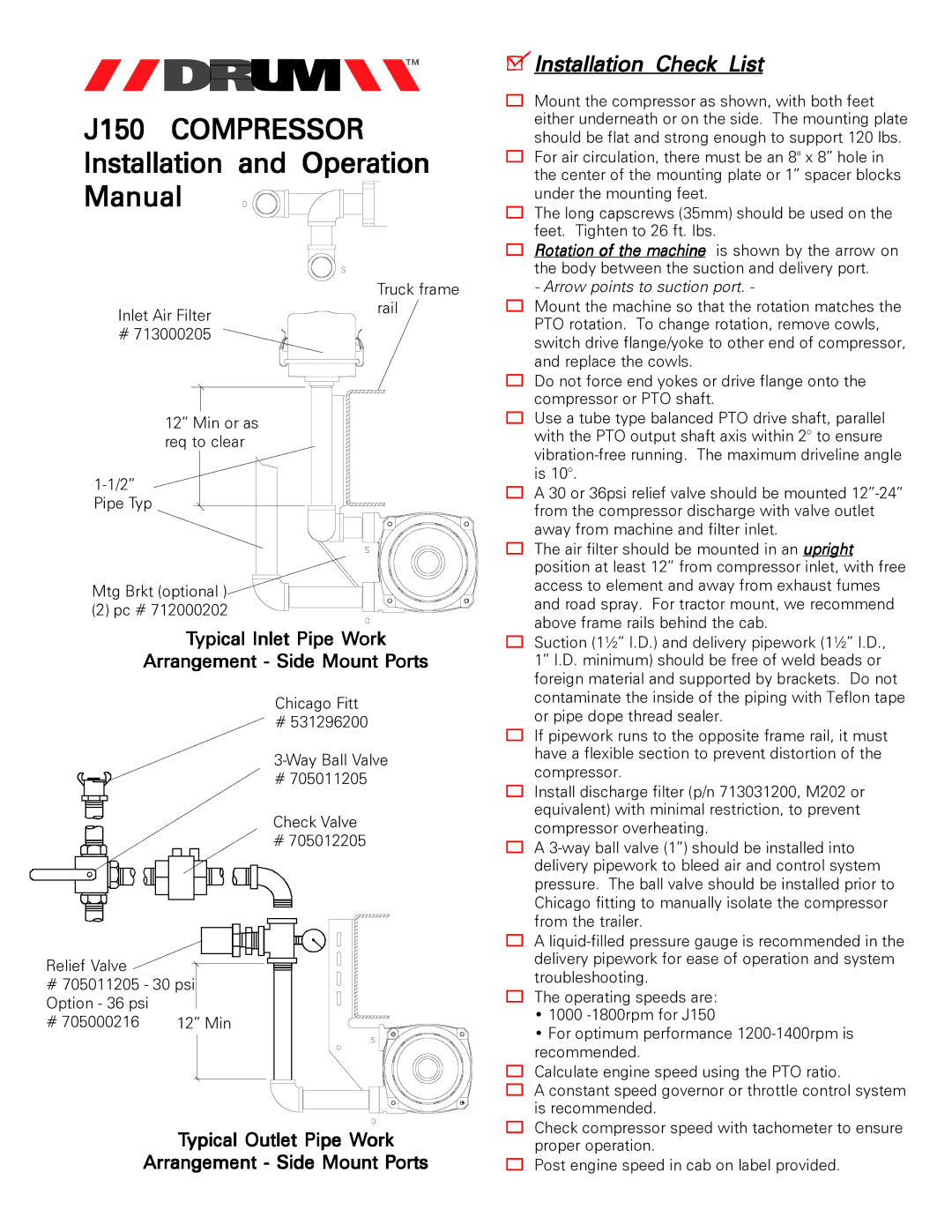
Truck frame
Inlet Air Filterrail
# 713000205
12” Min or as req to clear
Mtg Brkt (optional )![]()
(2) pc # 712000202
Typical Inlet Pipe Work
Arrangement - Side Mount Ports
Chicago Fitt
# 531296200
# 705011205
Check Valve
# 705012205
Relief Valve
#705011205 - 30 psi Option - 36 psi
# 705000216 | 12” Min |
Typical Outlet Pipe Work
Arrangement - Side Mount Ports
 Installation Check List
Mount the compressor as shown, with both feet either underneath or on the side. The mounting plate should be flat and strong enough to support 120 lbs.
For air circulation, there must be an 8" x 8” hole in the center of the mounting plate or 1” spacer blocks under the mounting feet.
The long capscrews (35mm) should be used on the feet. Tighten to 26 ft. lbs.
Rotation of the machine is shown by the arrow on the body between the suction and delivery port.
- Arrow points to suction port. -
Mount the machine so that the rotation matches the PTO rotation. To change rotation, remove cowls, switch drive flange/yoke to other end of compressor, and replace the cowls.
Do not force end yokes or drive flange onto the compressor or PTO shaft.
Use a tube type balanced PTO drive shaft, parallel with the PTO output shaft axis within 2° to ensure
A 30 or 36psi relief valve should be mounted
The air filter should be mounted in an upright position at least 12” from compressor inlet, with free access to element and away from exhaust fumes and road spray. For tractor mount, we recommend above frame rails behind the cab.
Suction (1½” I.D.) and delivery pipework (1½” I.D., 1” I.D. minimum) should be free of weld beads or foreign material and supported by brackets. Do not contaminate the inside of the piping with Teflon tape or pipe dope thread sealer.
If pipework runs to the opposite frame rail, it must have a flexible section to prevent distortion of the compressor.
Install discharge filter (p/n 713031200, M202 or equivalent) with minimal restriction, to prevent compressor overheating.
A
A
The operating speeds are:
•1000
•For optimum performance
Calculate engine speed using the PTO ratio.
A constant speed governor or throttle control system is recommended.
Check compressor speed with tachometer to ensure proper operation.
Post engine speed in cab on label provided.
